
BMW X5: Removing And Installing (Replacing) Trailer Module
IMPORTANT: Read and comply with notes on protection against electrostatic damage (ESD protection).
Necessary preliminary tasks:
- Remove flap in luggage compartment panel on right.
Lift back insulating mat.
Disconnect plug connection (1).
Unlock catch (2) and remove trailer module (3) from device carrier (4).
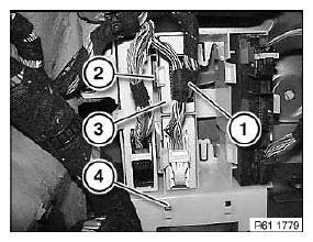
Fig. 235: Identifying Plug Connection, Catch, Trailer Module And Device
Carrier
Replacement:
Carry out programming/coding.
REMOVING AND INSTALLING (REPLACING) CONTROL UNIT FOR CAR ACCESS SYSTEM
IMPORTANT: Read and comply with notes on protection against electrostatic damage (ESD protection).
NOTE: The comfort access system is a radio-based system and can be interfered with by radio waves from other systems (e.g. mobile phone).
Necessary preliminary tasks:
- Disconnect battery negative lead.
- Remove trim panel for pedal assembly
Disconnect plug connection (1).
Release catches (2) and pull out control unit for Car Access System (3) in downward direction.
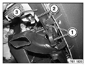
Fig. 236: Identifying Plug Connection, Catches And Car Access System
Replacement:
Carry out programming/coding.
Version with independent heating:
Initialize Telestart hand transmitter.
REMOVING AND INSTALLING/REPLACING CONTROL UNIT/MODULE FOR LEFT OR RIGHT SEAT ADJUSTMENT
IMPORTANT: Read and comply with notes on protection against electrostatic damage (ESD protection).
Necessary preliminary tasks:
- Disconnect battery negative lead.
NOTE: To facilitate installation/removal of control unit, move seat upwards fully.
Disconnect all plug connections on control unit for seat adjustment (1).
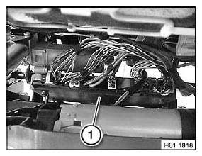
Fig. 237: Identifying Plug Connections On Control Unit For Seat Adjustment
Unlock retaining tabs (1) towards front and remove control unit for seat adjustment (2) in direction of arrow.
Installation:
Make sure control unit for seat adjustment (2) is correctly seated in mounting.
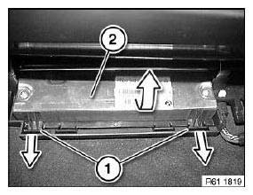
Fig. 238: Removing Control Unit For Seat Adjustment
Replacement:
Carry out programming/coding.
REMOVING AND INSTALLING/REPLACING JUNCTION BOX ELECTRONICS
IMPORTANT: Read and comply with notes on protection against electrostatic damage (ESD protection).
Necessary preliminary tasks:
- Disconnect battery negative lead.
- Remove trim for instrument panel, bottom left.
Release screws (1).
Remove air duct (2).
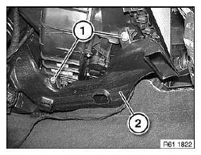
Fig. 239: Identifying Air Duct
Release screw (1).
Slacken wiring harness in cable holder (2).
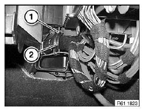
Fig. 240: Identifying Cable Holder
Release screw (1).
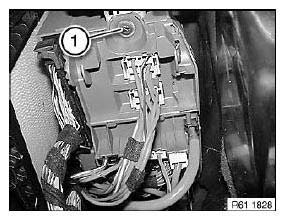
Fig. 241: Identifying Screw
Lever holders (1) at bulkhead out of fuse box (2) in direction of arrow.
Lower fuse box (2).
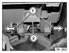
Fig. 242: Removing Holders
Disconnect plug connection (1).
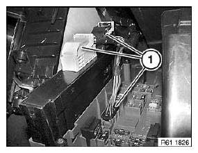
Fig. 243: Identifying Plug Connection
Release screws (1).
Pull junction box electronics (2) out of fuse box.
Installation:
Make sure junction box electronics (2) is correctly seated in fuse box plug connection.
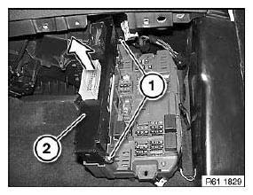
Fig. 244: Pulling Junction Box Electronics Out Of Fuse Box
Replacement:
Carry out programming/coding.
REMOVING AND INSTALLING/REPLACING FOOTWELL MODULE
IMPORTANT: Read and comply with notes on protection against electrostatic damage (ESD protection).
Necessary preliminary tasks:
- Disconnect battery negative lead.
- Remove footwell side trim panel on A-pillar, left.
Fold back carpet (1) in area of A-pillar a little.
Disconnect plug connection (2).
Release plastic nuts (3).
Pull footwell module (4) forwards a little.
Disconnect plug connection (5).
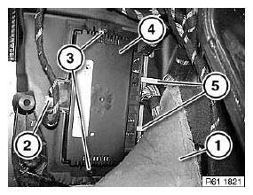
Fig. 245: Identifying Plug Connection And Footwell Module
Replacement:
Carry out programming/coding.
READ NEXT:
 Initializing Rain/Light Sensor
NOTE: Initialization is necessary:
After replacing windshield
When installing a used rain/light sensor
NOTE:
Connect BMW diagnosis system
Initialize rain/light sensor.
REPLACING OPTICAL ELEME
Relays
RELAY CARRIER
Place special tool 61 1 153 on relay carrier (1) and carefully pull in
direction of arrow until retaining lugs (2) on
relay carrier are raised.
Fig. 257: Pulling Relay Carrier
Pull rel
Windscreen Wipers
OVERVIEW OF WINDSCREEN WIPER, WINDSCREEN WASHER AND HEADLIGHT
WASHER SYSTEMS
Fig. 262: Overview Of Windscreen Wiper, Windscreen Washer And Headlight
Washer Systems
Rear window wiper blade
Wiper a
SEE MORE:
Overview Of Airbag Modules, Airbag Control Unit, Belt Tensioners
Fig. 64: Location Of Airbag Modules
Safety battery terminal
Side airbag, front seat, left/right
Belt tensioner, front left/right
Airbag unit, passenger side
Airbag module, drivers side
Head airbag, left/right
On-board Computer
REMOVING AND INSTALLING/REPLACING OUTSIDE TEMPERATURE SENSOR
Bonding Steel Parts
IMPORTANT: Conform with safety precautions !
Overview of topics:
Equipment
Expiry date of adhesive
Grinding and cleaning
Gluing coat
Hardening times
After treatment of bonding surfaces
Disposing of adhesive
1.0 Equipment
Emery paper
Cleaning agent: Isopropanol, acetone or spirit
Adhesiv
