
BMW X5: Initializing Rain/Light Sensor
NOTE: Initialization is necessary:
- After replacing windshield
- When installing a used rain/light sensor
NOTE:
- Connect BMW diagnosis system
- Initialize rain/light sensor.
REPLACING OPTICAL ELEMENT FOR SOLAR RAIN/LIGHT SENSOR
IMPORTANT: Read and comply with notes on protection against electrostatic damage (ESD protection).
Necessary preliminary tasks:
Remove solar rain/light sensor.
Optical element can only be replaced in the following equipment specifications:
- E70 without head-up display
Carefully expand catches (1) of solar rain/light sensor (2).
Remove optical element (3).
Installation:
Remove protective cover from replacement optical element.
Catches (1) of solar sensor (2) must not be damaged.
Observe laser marking (4) of fitting aid.
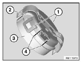
Fig. 246: Identifying Catches, Solar Rain/Light Sensor And Optical Element
Carry out initialization.
Carry out programming/coding if installing a different windscreen type.
REPLACING RAIN/LIGHT SOLAR SENSOR
IMPORTANT: Read and comply with notes on protection against electrostatic damage (ESD protection).
Expand two-part mirror base cover (1) by pressing from below and detach.
Feed out two-part mirror base cover (1) and remove.
If necessary, remove interior rearview mirror.
NOTE: Catches of two-part mirror base cover (1) must not be damaged.
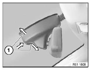
Fig. 247: Expanding Two-Part Mirror Base Cover
Disconnect plug connection (1).
Unlock metal spring (3) in direction of arrow.
Pull off solar rain/light sensor (2) from windscreen.
Installation:
Connect plug (1) only after fitting sensor.
Pull off protective cover from new solar rain/light sensor.
Align solar rain-light sensor (2) and press firmly on windscreen.
Pay attention to mechanical coding (6).
Press metal spring (3) centrally to ensure that retaining element (5) engages correctly in both hooks (4).
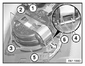
Fig. 248: Unlocking Metal Spring
Clean windscreen in area (A) of fastening element and remove residues of silicone.
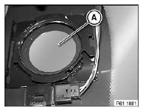
Fig. 249: Identifying Windscreen Cleaning Area
Replacement:
- Carry out programming/coding.
- Carry out initialization.
REMOVING AND INSTALLING/REPLACING CONTROL UNIT FOR COMFORT ACCESS SYSTEM (PASSIVE GO)
IMPORTANT: Read and comply with notes on protection against electrostatic damage (ESD protection).
Necessary preliminary tasks:
- Remove flap in luggage compartment panel on right.
Lift back insulating mat (1).
Disconnect plug connection (3).
Unlock catch (2) and remove control unit for Comfort Access System (4) from device carrier (5).
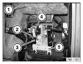
Fig. 250: Identifying Insulating Mat, Plug Connection And Device Carrier
Replacement:
Carry out programming/coding.
REMOVING AND INSTALLING/REPLACING INTERIOR ANTENNA FOR COMFORT ACCESS SYSTEM
Necessary preliminary tasks:
- Remove Car Communication Computer.
Release screw (1).
Release screw (2) through opening (3).
Pull out interior antenna for comfort access system (4).
Disconnect plug connection.
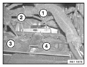
Fig. 251: Identifying Interior Antenna For Comfort Access System (4)
REMOVING AND INSTALLING/REPLACING INTERIOR ANTENNA FOR COMFORT ACCESS SYSTEM (REAR CENTRE CONSOLE)
Necessary preliminary tasks:
- Remove rear center console trim.
Unlock retaining hook (1) and remove interior antenna for comfort access system (2).
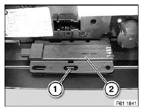
Fig. 252: Identifying Retaining Hook And Interior Antenna For Comfort Access
System
REMOVING AND INSTALLING/REPLACING INTERIOR ANTENNA FOR COMFORT ACCESS SYSTEM ON LEFT OR RIGHT
Necessary preliminary tasks:
- Fold back luggage compartment floor trim panel
Release expansion rivet (1).
Fold back luggage compartment tray (2) slightly.
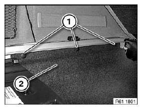
Fig. 253: Identifying Expansion Rivet And Luggage Compartment Tray
Disconnect plug connection (1).
Release screws (2).
Remove interior antenna (3).
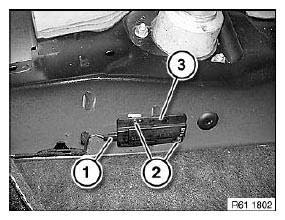
Fig. 254: Identifying Plug Connection And Interior Antenna
REMOVING AND INSTALLING/REPLACING BUMPER ANTENNA FOR COMFORT ACCESS SYSTEM
Reach behind bumper trim and disconnect plug connection (2).
Press catches (1) and pull out bumper antenna for Comfort Access System (3) in direction of arrow.
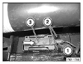
Fig. 255: Pulling Out Bumper Antenna For Comfort Access System
VEHICLE PROGRAMMING AND CODING
Select menu item (1).
Select corresponding procedure from selection list.
Example:
- Preparation and subsequent evaluation of vehicle programming
- Start a Program session
- Sequence of BMW/MINI vehicle programming and coding
- BMW/MINI Car & Key Memory
- BMW/MINI initialization
- BMW/MINI service functions in Progman
- ...
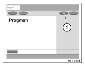
Fig. 256: Display BMW Vehicle Programming And Coding
NOTE: In order to avoid incorrect programming procedures and error messages, it is essential when working with the Progman programming system always to use the latest Progman version.
READ NEXT:
 Relays
RELAY CARRIER
Place special tool 61 1 153 on relay carrier (1) and carefully pull in
direction of arrow until retaining lugs (2) on
relay carrier are raised.
Fig. 257: Pulling Relay Carrier
Pull rel
Windscreen Wipers
OVERVIEW OF WINDSCREEN WIPER, WINDSCREEN WASHER AND HEADLIGHT
WASHER SYSTEMS
Fig. 262: Overview Of Windscreen Wiper, Windscreen Washer And Headlight
Washer Systems
Rear window wiper blade
Wiper a
Rear Window Wiper
OVERVIEW OF WINDSCREEN WIPER, WINDSCREEN WASHER AND HEADLIGHT
WASHER SYSTEMS
Fig. 273: Overview Of Windscreen Wiper, Windscreen Washer And Headlight
Washer Systems
Rear window wiper blade
Wiper a
SEE MORE:
Removing And Installing/Replacing Rocker Arms On Left Inlet Side (N62
From 9/03 And N62TU)
Special tools required:
11 9 470
11 9 473
(cylinder bank 5 to 8)
Removal of rocker arms is described separately from installation.
Necessary preliminary tasks:
Remove servomotor for left eccentric shaft.
Remove ignition coils on cylinder bank 5 to 8.
Remove left cylinder head cover.
Remov
Mounting Engine On Assembly Stand (N52K)
Special tools required:
00 1 450 ASSEMBLY STAND
11 3 370
11 4 440
11 9 261
11 9 265
IMPORTANT: Aluminium screws/bolts must be replaced each time they are
released.
The end faces of aluminium screws/bolts are painted blue for the purposes of
reliable identification.
Jointing torque and angl
