
BMW X5: Removing And Installing/Replacing Exhaust Camshaft (N52K)
Special tools required:
- 00 9 120
- 11 4 350
- 11 4 461
- 11 4 462
- 11 4 463
- 11 9 000
IMPORTANT: It is absolutely essential to follow an exact procedure for removing and installing the exhaust camshaft.
Risk of damage! The upper and lower bearing banks must be tensioned with a total of six special tools 11 4 461.
Necessary preliminary tasks:
- Remove cylinder head cover
- Remove exhaust adjustment unit
- Adjust valve timing
The screw connection of the bearing banks must be released from the outside inwards.
Lift out upper and lower bearing banks (1) with exhaust camshaft.
Remove upper bearing bank (1).
Remove exhaust camshaft from lower bearing bank.

Fig. 167: Upper And Lower Bearing Banks
IMPORTANT: Markings of inlet and exhaust camshafts are different.
Mixing up the inlet and exhaust camshaft will result in engine damage.
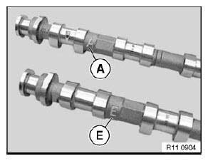
Fig. 168: Markings Of Inlet And Exhaust Camshafts
Check plain compression rings (1) for damage and replace if necessary.
Plain compression rings (1) are engaged at joint.
Press plain compression rings (1) apart upwards and downwards and removed towards front.
IMPORTANT: Plain compression rings (1) can easily break.
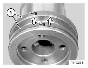
Fig. 169: Removing Plain Compression Rings
IMPORTANT: Removal on engine: Set engine to firing TDC at 1st cylinder.
Removed cylinder head: When using special tool 11 9 000, it will be necessary to remove the aluminium profile insert.
Mounting bearing bank:
Pre-install special tool 11 4 462 on cylinder no. 2.
Insert special tool 11 4 463 in screw connection of cylinder head cover.
IMPORTANT: Special tool 11 4 463 is a special screw.
Press down cam followers (3) on cylinder no. 2 with spindle nut (2) of special tool 11 4 462.
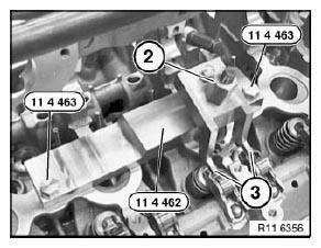
Fig. 170: Cam Followers, Spindle Nut And Special Tools
Installation:
Before mounting the exhaust camshaft on the correct cam follower seat (1), pay attention to the hydraulic valve clearance adjustment element and the valve.
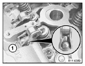
Fig. 171: Cam Follower Seat
Position lower bearing bank (1) with exhaust camshaft (2) cam followers.
Align exhaust camshaft (2).
Cylinder nos. 2 and 4 are at valve overlap.
Cams (3) on cylinder no. 1 point upwards at an angle.
Part number (4) on twin surface of exhaust camshaft (2) points upwards.
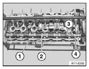
Fig. 172: Lower Bearing Bank, Exhaust Camshaft With Part Number And Cams
IMPORTANT: There must be no adhesive residues in the cylinder head tapped holes.
Clean tapped holes.
Fit upper bearing bank (1).
Insert bolts dry.
Tension down upper bearing bank (1) with exhaust camshaft at bearing points 3 and 5 through a 1/2 bolt turn.
Join exhaust camshaft to upper and lower bearing banks (1) with torque wrench (2) from inside outwards to 8 Nm.
Release all screws of upper bearing bank (1) from outside inwards by 90º.
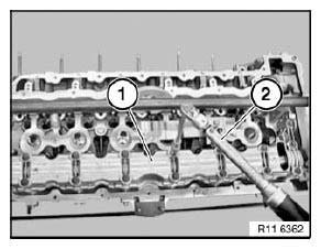
Fig. 173: Upper And Lower Bearing Banks
Installation:
Upper and lower bearing banks must be aligned to each other at ground surfaces (1 and 2).
Make sure that the thrust piece and the legs of special tools 11 4 461 rest on the milled surfaces.
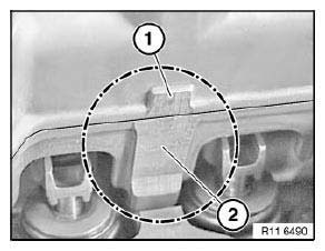
Fig. 174: Ground Surfaces
NOTE: Schematic depiction of special tool 11 4 461 at upper bearing bank (1) and lower bearing bank (2).
Pretension all special tools 11 4 461 with special tool 11 4 350 only.
IMPORTANT: Tighten screw (3) on thrust piece to 2 Nm. Risk of damage!
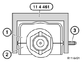
Fig. 175: Screw, Upper And Lower Bearing Bank
Position special tool 11 4 461 over screw connection of bearing banks.
Make sure that the legs rest exactly on the ground surfaces of the upper bearing bank (2) and lower bearing bank (1).
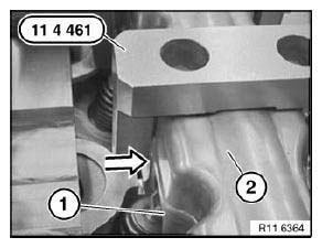
Fig. 176: Special Tool (11 4 461), Upper And Lower Bearing Bank
Initially tighten screw of special tool 11 4 461 to ground surfaces of upper bearing bank (1) and lower bearing bank (2).
IMPORTANT: Tighten screws on thrust piece to 2 Nm. Risk of damage!
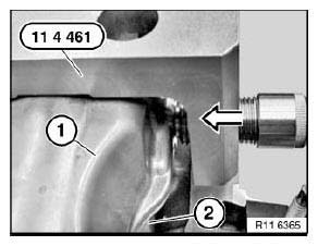
Fig. 177: Tightening Special Tool (11 4 461) Screw On Upper And Lower Bearing
Bank Ground Surfaces
IMPORTANT: Set special tool 11 4 350 to 2 Nm.
Pretension all special tools 11 4 461 with special tool 11 4 350 only.
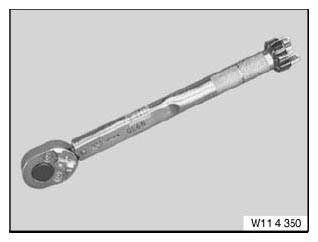
Fig. 178: Special Tool
Mount special tools 11 4 461 with screw (1) to inside of cylinder head.
Mount special tool 11 4 461 with screw facing outwards on cylinder no. 2.
Position special tools 11 4 461 so that screw connections (2) of bearing bank are easily accessible.
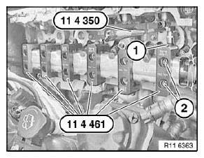
Fig. 179: Special Tools (11 4 461) And (11 4 350)
Tighten upper and lower bearing banks with special tool 00 9 120.
Tightening torque: 11 31 1AZ.
IMPORTANT: Remove special tool 11 4 461 only when exhaust camshaft screw connection is completed.
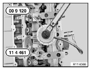
Fig. 180: Special Tools (11 4 461) And (00 9 120)
Assemble engine.
READ NEXT:
 Replacing Timing Chain (N52K)
Special tools required:
00 9 140
11 0 300
11 4 280
11 4 281
11 4 282
11 4 283
11 4 360
11 4 362
11 5 200
11 9 280
Necessary preliminary tasks:
Remove cylinder head cover
Remove all spar
Adjusting Timing Of Camshaft(s) (N52K)
Special tools required:
00 9 120 TORQUE ANGLE MEASURING DIAL
00 9 250 TORSION ANGLE WRENCH WITH FLEXIBLE EXTENSION
11 0 300
11 4 280
11 4 281
11 4 282
11 4 283
11 4 290
11 9 340
Necessary p
Rocker Arm With Bearing Mount
REMOVING AND INSTALLING/REPLACING ALL CAM FOLLOWERS (N52K)
Special tools required:
11 4 480
Necessary preliminary tasks:
Remove cylinder head cover
Remove intermediate lever
Remove exhaust cams
SEE MORE:
Removing And Installing/Replacing Intermediate Levers (N52K)
Special tools required:
11 4 270
11 4 450
11 4 481
IMPORTANT: Aluminium screws/bolts must be replaced each time they
are released.
The end faces of aluminium screws/bolts are painted blue for the purposes of
reliable identification.
Jointing torque and angle of rotation must be observed with
Loading
Safety information
Warning
High gross weight can overheat the tires, damage
them internally and cause a sudden tire
pressure loss. Driving characteristics may be
negatively impacted, reducing lane stability,
lengthening the braking distances and changing
the steering response. There is a risk of acc
