
BMW X5: Adjusting Timing Of Camshaft(s) (N52K)
Special tools required:
- 00 9 120 TORQUE ANGLE MEASURING DIAL
- 00 9 250 TORSION ANGLE WRENCH WITH FLEXIBLE EXTENSION
- 11 0 300
- 11 4 280
- 11 4 281
- 11 4 282
- 11 4 283
- 11 4 290
- 11 9 340
Necessary preliminary tasks:
- Remove cylinder head cover
Remove fastener (1) in direction of arrow.
Installation:
Install fastener (1) with bore facing outwards.
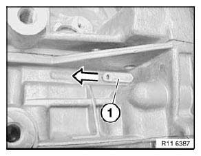
Fig. 198: Fastener
Rotate crankshaft at central bolt into TDC position.
Slide special tool 11 0 300 in direction of arrow into special tool bore and secure crankshaft.
IMPORTANT: On vehicles with optional extra SA205 (automatic transmission), there is a large bore for the TDC position shortly before the special tool bore. This bore can be confused with the special tool bore.
If the flywheel is secured in the correct special tool bore with special tool 11 0 300 , the engine can no longer be moved at the central bolt.
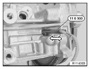
Fig. 199: Securing Crankshaft Using Special Tool (11 0 300)
With 1st cylinder in firing TDC position, cams of inlet camshaft (1) at 1st cylinder point upwards at an angle.
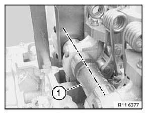
Fig. 200: Inlet Camshaft
Part numbers (2) on inlet and exhaust camshafts (1) point upwards.
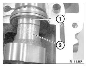
Fig. 201: Part Numbers On Inlet And Exhaust Camshafts
With 1st cylinder in firing TDC position, cams of exhaust camshaft (3) at 6th cylinder point downwards at an angle.
Cam follower (1) is not actuated.
NOTE: When the engine is installed, the position of the exhaust camshaft (3) for the timing can only be checked with a mirror.
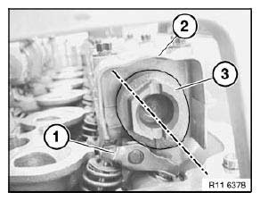
Fig. 202: Exhaust Camshaft And Cam Follower
Secure special tool 11 4 283 to cylinder head with bolts (1).
NOTE: Fit special tool 11 4 282 underneath on side of inlet camshaft.
Mount special tool 11 4 281 on inlet and exhaust camshafts.
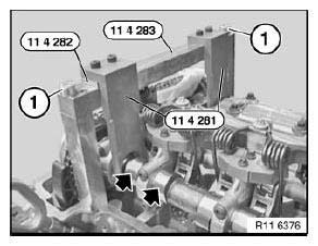
Fig. 203: Cylinder Head Bolts And Special Tools (11 4 282) And (11 4 281)
Release central bolts (1).
Release central bolts (1) with special tool 11 4 280 only.
Release chain tensioner (2) (have a cleaning cloth ready).
NOTE: Picture in CAD and does not show special tools.
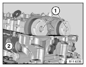
Fig. 204: Central Bolts And Chain Tensioner
Turn sensor gears (2) in direction of arrow until locating pins (1) on special tool 11 4 290 match up.
Slide on special tool 11 4 290 in direction of arrow.
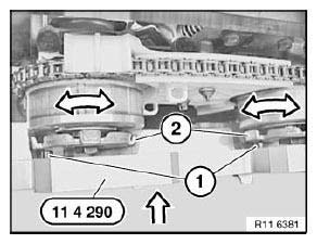
Fig. 205: Sensor Gears, Locating Pins And Special Tool (11 4 290)
Secure special tool 11 4 290 with bolts (1).
Screw special tool 11 9 340 into cylinder head.
Pretension timing chain with special tool 00 9 250 to 0.6 Nm.
Secure both central bolts of inlet and exhaust adjustment units with special tool 00 9 120 to inlet and exhaust camshafts.
Tightening torque: 11 36 1AZ.
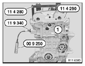
Fig. 206: Special Tools (00 9 250), (11 9 340) And (11 4 290)
Assemble engine.
READ NEXT:
 Rocker Arm With Bearing Mount
REMOVING AND INSTALLING/REPLACING ALL CAM FOLLOWERS (N52K)
Special tools required:
11 4 480
Necessary preliminary tasks:
Remove cylinder head cover
Remove intermediate lever
Remove exhaust cams
Valves With Springs
REMOVING AND INSTALLING/REPLACING ALL VALVES (N52K)
Special tools required:
11 4 480
Necessary preliminary tasks:
Remove cylinder head
Remove intermediate lever
Remove eccentric shaft
Remove i
SEE MORE:
Removing And Installing/Replacing Rear Left Or Right Shock Absorber
NOTE: Read and comply with Information on replacing shock
absorbers.
Version with Vertical Dynamics Management:
IMPORTANT: Handle the spring strut with care so as to avoid damaging
the control unit (1)
and control valve (2).
Fig. 112: Identifying Control Unit And Control Valve
Necessary prelimina
Reversing Camera
INSTRUCTIONS FOR ADAPTING ADJUSTMENT UNIT FOR REVERSING CAMERA
(CORGHI KDS QUICK - ACTION CLAMP)
NOTE: The operation is described for the left-hand side; proceed in the
same way for the right-hand side.
Remove support plate (1) from spindle (2).
Replace spindle (2) by spindle (3).
Press support p
