
BMW X5: Removing And Installing/Replacing Oil Pump (N52K)
Necessary preliminary tasks:
- Remove oil sump
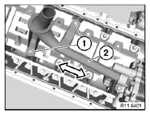
Release screws (1).
Tightening torque: 11 41 1AZ.
Installation:
Replace aluminium screws.
Remove intake pipe (2) in direction of arrow.
Installation:
Replace sealing ring.
NOTE: To release bolt (1), insert a 6 mm drill bit between sprocket wheel and oil pump housing.
Release bolt (1).
Tightening torque: 11 41 6AZ.
Release screws (2).
Tightening torque: 11 41 5AZ.
Installation:
Replace aluminium screws.
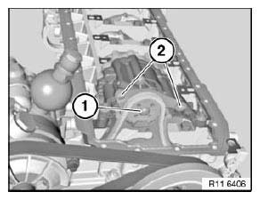
Fig. 246: Bolt And Screw
IMPORTANT: Observe different screw lengths.
Release screws (1).
Tightening torque: 11 41 2AZ.
Tightening torque: 11 41 3AZ.
Installation:
Replace aluminium screws.
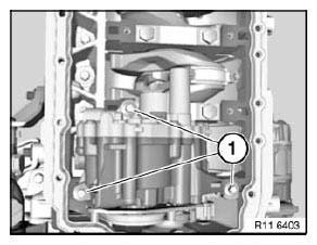
Fig. 247: Screws
Detach sprocket wheel (1) in direction of arrow.
NOTE: Chain tensioner presses timing chain (3) upwards.
Do not remove sprocket wheel (1).
Remove oil pump (2) in direction of arrow.
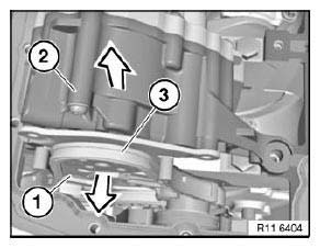
Fig. 248: Removing Sprocket Wheel
Installation:
Check spacers (1) for secure seating and damage; replace if necessary.
Align twin surface (3) on oil pump (2) to sprocket wheel (4).
Install oil pump (2).
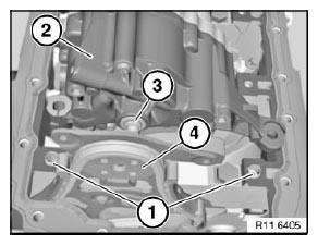
Fig. 249: Spacers, Oil Pump And Sprocket Wheel
Assemble engine.
READ NEXT:
 Removing And Installing/Replacing Chain Module For Oil Pump/Vacuum Pump
(N52K)
Removing And Installing/Replacing Chain Module For Oil Pump/Vacuum Pump
(N52K)
Special tools required:
00 9 140
11 0 290
11 0 300
11 4 120
11 4 280
11 4 360
11 4 362
11 4 440
11 5 200
11 9 280
IMPORTANT: Aluminium-magnesium materials.
No steel screws/bolts may be us
Water Pump With Drive
REMOVING AND INSTALLING/REPLACING WATER PUMP (N52K)
WARNING: Danger of scalding!
Only perform this work after engine has cooled down.
Recycling:
Catch and dispose of drained coolant in a suitable cont
Thermostat And Connections
REMOVING AND INSTALLING/REPLACING COOLANT THERMOSTAT (N52K)
WARNING: Danger of scalding!
Only perform this work after engine has cooled down.
Recycling
Catch and dispose of drained coolant in a suitab
SEE MORE:
Opening Plug Housings And Removing Contacts Of Different Plug
Systems
Special tools required:
61 0 300
61 0 400
61 1 150
Abbreviations and what they mean:
ABBREVIATIONS MEANINGS
Ultrasonic-welded connectors:
Ultrasonic-welded connectors (1) can be identified by the welds (2) on their
longitudinal side.
The contacts of these connectors cannot be replaced. Repla
Exterior mirrors
General information
The mirror on the front passenger side is more
curved than the driver's side mirror.
The mirror setting is stored for the driver profile
currently in use. When a driver profile is selected,
the stored position is called up automatically.
The current exterior mirror position can
