
BMW X5: Removing And Installing/Replacing Chain Module For Oil Pump/Vacuum Pump (N52K)
Special tools required:
- 00 9 140
- 11 0 290
- 11 0 300
- 11 4 120
- 11 4 280
- 11 4 360
- 11 4 362
- 11 4 440
- 11 5 200
- 11 9 280
IMPORTANT: Aluminium-magnesium materials.
No steel screws/bolts may be used due to the threat of electrochemical corrosion.
A magnesium crankcase requires aluminium screws/bolts exclusively.
Aluminium screws/bolts must be replaced each time they are released.
The end faces of aluminium screws/bolts are painted blue for the purposes of reliable identification.
Jointing torque and angle of rotation must be observed without fail (risk of damage).
Necessary preliminary tasks:
- Remove cylinder head cover
- Remove oil sump
- Remove drive belt
- Remove drive belt tensioner
- Remove vibration damper
- Remove sealing cover for vacuum pump
Procedure on installed engine:
Turn sprocket wheel (3) with central bolt at crankshaft into position until special tool 11 0 290 can be secured.
Simultaneously secure special tool 11 0 290 to sprocket wheel (3) and special tool 11 4 362.
Release screw (2) for sprocket wheel (3).
Tightening torque: 11 66 2AZ.
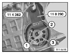
Fig. 250: Special Tool (11 4 362) And (11 0 290), Screw And Sprocket Wheel
Press timing chain with chain tensioner (1) in direction of arrow.
Disconnect timing chain with special tool 11 4 120.
Feed out sprocket wheel (3) at hexagon head (4) of vacuum pump.
Installation:
If the chain module is replaced, a mounting bar (2) is already pre-installed.
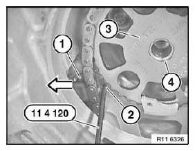
Fig. 251: Pressing Piston With Special Tools (11 6 261)
NOTE: To release bolt (1), insert a 6 mm drill bit between sprocket wheel and oil pump housing.
Release screw (1) for sprocket wheel.
Tightening torque: 11 41 6AZ.
Release screws (2) for chain module.
Tightening torque: 11 41 5AZ.
Installation:
Replace aluminium screws.
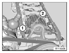
Fig. 252: Bolt And Screw
Secure crankshaft and camshaft with special tools 11 0 300 and 11 4 280.
IMPORTANT: Do not remove special tools 11 0 300 and 11 4 280 to release central bolt (1).
Employ a second person for gripping when releasing central bolt (1).
Screw special tool 11 9 280 onto hub of vibration damper.
Release central bolt (1).
Tightening torque: 11 21 1AZ.
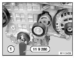
Fig. 253: Central Bolt With Special Tool (11 9 280)
Installation:
Replace central bolt (1).
Remove hub (2) towards front.
Installation:
Replace crankshaft radial seal at front.
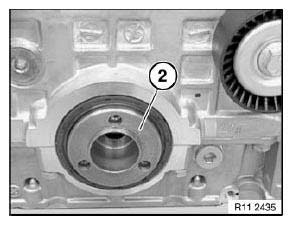
Fig. 254: Hub
Open screw plug on bedplate.
Tightening torque: 11 11 8AZ.
Installation:
Replace aluminium screws.
Release screw for chain module (1).
Tightening torque: 11 41 4AZ.
Installation:
Replace aluminium screws.
Remove chain module (1) in direction of arrow.
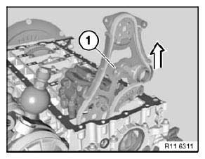
Fig. 255: Removing Chain Module
IMPORTANT: Note installation direction of sprocket wheel (2).
Collar (see arrow) on sprocket wheel (2) points to engine.
Incorrect assembly will result in engine damage.
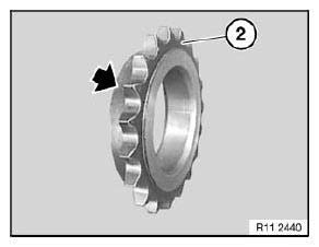
Fig. 256: Collar On Sprocket Wheel
Procedure on removed engine:
NOTE: Engine is mounted on special tool 11 4 440.
Release screw (1) for sprocket wheel.
Tightening torque: 11 66 2AZ.
Release screw (2) for sprocket wheel.
Tightening torque: 11 41 6AZ.
Release central bolt (3).
Tightening torque: 11 21 1AZ.
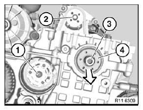
Fig. 257: Releasing Central Bolt
Installation:
Mark central bolt (3) with a colored dot.
Replace central bolt (3).
Remove hub (4) towards front.
All:
Install hub with new central bolt.
Tighten down special tool 11 5 200 with screws (1) to hub.
Do not remove special tools 11 0 300 and 11 4 280.
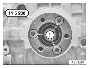
Fig. 258: Screws With Special Tool (11 5 200)
Remove tensioner for drive belt.
Screw in special tool 11 4 362 from special tool kit 11 4 360.
Mount special tool 11 9 280 on 11 5 200.
Support special tool 11 9 280 on special tool 11 4 362.
Special tool 11 0 300 secures crankshaft.
Tighten central bolt to jointing torque.
Tightening torque: 11 21 1AZ.
Mark central bolt and hub with paint.
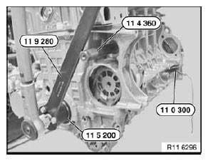
Fig. 259: Special Tools (11 9 280), (11 0 300), (11 4 360) And (11 5 200)
Mark special tools with colored line (1).
See picture.
IMPORTANT: Do not remove the special tool while tightening the central bolt to torsion angle.
Risk of damage!
If necessary, tighten central bolt to torsion angle with special tool 00 9 140.
Tightening torque: 11 21 1AZ.
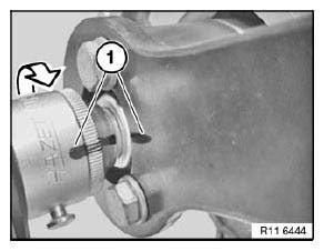
Fig. 260: Marking Special Tools With Colored Line
Installation:
Replace crankshaft radial seal at front.
Assemble engine.
READ NEXT:
 Water Pump With Drive
REMOVING AND INSTALLING/REPLACING WATER PUMP (N52K)
WARNING: Danger of scalding!
Only perform this work after engine has cooled down.
Recycling:
Catch and dispose of drained coolant in a suitable cont
Thermostat And Connections
REMOVING AND INSTALLING/REPLACING COOLANT THERMOSTAT (N52K)
WARNING: Danger of scalding!
Only perform this work after engine has cooled down.
Recycling
Catch and dispose of drained coolant in a suitab
Intake Manifold
REMOVING AND INSTALLING AIR INTAKE MANIFOLD (N52K)
Necessary preliminary tasks:
Remove Tension Strut
Remove Intake Filter Housing
Remove Ignition Coil Cover
Open holder (2).
Disconnect plug conn
SEE MORE:
Brake Lines
OVERVIEW OF BRAKE LINES
1. Brake hose, front.
2. Brake tubes.
3. Brake hose, rear, to body.
4. Brake hose, rear, to wheel brake cylinder.
REPLACING ALL BRAKE PIPES
Special tools required:
34 5 100
NOTE: The brake lines are only supplied in the straight version and
correct length with
connectin
Active Cruise Control with
Stop&Go function ACC
Principle
Using the Cruise Control, a desired speed and a
distance to a vehicle ahead can be adjusted using
the buttons on the steering wheel.
General information
The system maintains the set speed on clear
roads. The vehicle accelerates or brakes automatically.
If a vehicle is driving ahead of you
