
BMW X5: Removing And Installing/Replacing Light Control Unit
Necessary preliminary tasks:
- Remove left fresh-air grille.
Press out light control unit (1) from inside.
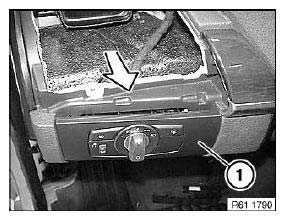
Fig. 175: Pressing Out Light Control Unit
Disconnect plug connection (1).
Remove light control unit.
Installation:
Make sure retainers (2) are correctly seated on trim of light control unit.
If necessary, replace faulty retainers.
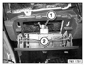
Fig. 176: Identifying Plug Connection And Retainers
Replacement:
Release screws (1).
Remove light control unit (2) from trim (3).
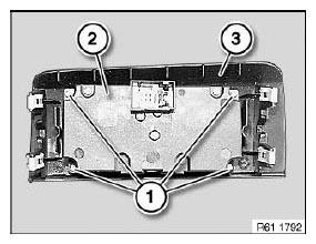
Fig. 177: Identifying Light Control Unit And Trim
REMOVING AND INSTALLING OR REPLACING ROOF SWITCH CENTRE
Special tools required:
- 00 9 317
- 00 9 340
IMPORTANT: Read and comply with notes on protection against electrostatic damage (ESD protection).
IMPORTANT: Follow instructions for handling light bulbs (interior lights).
Carefully lever out trim (1) with special tool 00 9 340.
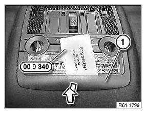
Fig. 178: Levering Out Trim With Special Tool 00 9 340
Unlock retaining clip (1).
Lever out roof switch center with special tool 00 9 317.
Disconnect plug connections underneath.
Installation:
Before installing, fit trim on roof switch center.
Make sure trim is correctly seated.
Position roof switch cluster at an angle of 90º with respect to the headliner and attach.
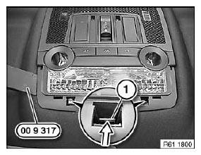
Fig. 179: Unlocking Retaining Clip
IMPORTANT: Disconnecting the plug connection for the hands-free microphone or emergency SOS call button results in fault memory entries in the telephone control unit (limitation in the emergency SOS call system).
After fitting, read out fault memory and if necessary delete entries.
Replacement:
- If necessary, modify bulbs.
- If necessary, remove hands-free microphone.
- Carry out programming/coding.
- If necessary, initialize slide/tilt sunroof.
REMOVING AND INSTALLING/REPLACING CENTRE CONSOLE SWITCH CLUSTER
Necessary preliminary tasks:
- Remove middle trim for instrument panel.
Disconnect plug connection (1) and expose ribbon cable up to center console switch cluster (2).
Unclip center console switch cluster (2) at retaining points (3).
Remove center console switch cluster (2) in direction of arrow from instrument panel trim.
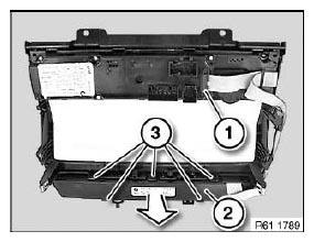
Fig. 180: Removing Centre Console Switch Cluster From Instrument Panel Trim
REMOVING AND INSTALLING/REPLACING SWITCH FOR HAZARD WARNING FLASHERS/CENTRAL LOCKING
Special tools required:
- 00 9 340
Lever out switch for hazard warning system/central locking (1) with special tool 00 9 340 and pull back.
Disconnect associated plug connection and remove switch for hazard warning system/central locking (1).

Fig. 181: Identifying Switch For Hazard Warning System/Central Locking
REMOVING AND INSTALLING/REPLACING SWITCH FOR LEFT OR RIGHT SEAT HEATING (REAR)
Special tools required:
- 00 9 340
Unclip trim with special tool 00 9 340.
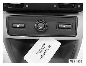
Fig. 182: Uncliping Trim With Special Tool 00 9 340
Disconnect plug connection (1).
Press locks (2) together and press switches for seat heating out of trim (3).
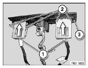
Fig. 183: Pressing Seat Heating Switches Out Of Trim
REPLACING ROCKER SWITCH FOR SIDE WINDOW OPERATION (REAR)
Special tools required:
- 00 9 317
Lever rocker switch (1) with special tool 00 9 317 upwards out of armrest.
Disconnect plug connection.
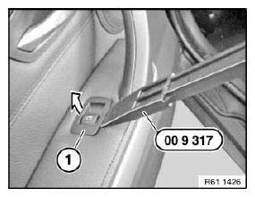
Fig. 184: Removing Rocker Switch
Installation:
Retaining hooks (1) of rocker switch (2) must not be damaged.
Make sure rocker switch (2) is correctly seated.
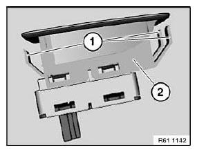
Fig. 185: Identifying Hooks Of Rocker Switch
REMOVING AND INSTALLING/REPLACING POWER WINDOW SWITCH (DRIVER'S SIDE)
Special tools required:
- 00 9 317
Lever rocker switch (1) with special tool 00 9 317 upwards out of armrest.
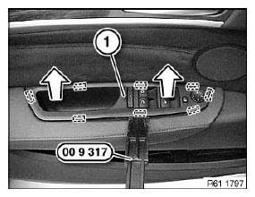
Fig. 186: Removing Rocker Switch
Disconnect plug connection (1).
Installation:
Make sure retainers (2) are correctly seated on power window switch.
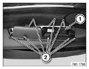
Fig. 187: Identifying Plug Connection And Retainers
REMOVING AND INSTALLING/REPLACING POWER WINDOW SWITCH (PASSENGER SIDE)
Special tools required:
- 00 9 317
Lever rocker switch (1) with special tool 00 9 317 upwards out of armrest.
Disconnect plug connection.
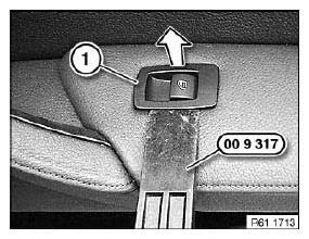
Fig. 188: Removing Rocker Switch
Installation:
Retaining hooks (1) of rocker switch (2) must not be damaged.
Make sure rocker switch (2) is correctly seated.

Fig. 189: Identifying Hooks Of Rocker Switch
READ NEXT:
 Removing And Installing/Replacing Aux Connection Socket
Special tools required:
00 9 323
Necessary preliminary tasks:
Open storage box
Unclip trim (1) with special tool 00 9 323 at retaining points (2).
Disconnect associated plug connections.
Fig.
Removing And Installing/Replacing Switch For Unlocking Glovebox
Necessary preliminary tasks:
Remove decorative strip from middle fresh-air grille.
Unlock catches (1).
Press switch (2) out of decorative strip.
Fig. 212: Pressing Switch Out Of Decorative Strip
Horn
REMOVING AND INSTALLING/REPLACING LEFT FANFARE HORN
Necessary preliminary tasks:
Remove front bumper trim.
Release nut (1) and feed out holder (2) with fanfare horn.
Tightening torque.
Disconnect
SEE MORE:
Automatic deactivation of
the front passenger airbags
Principle
The system reads if the front passenger seat is
occupied by measuring the human body's resistance.
Front, knee, and side airbag on the front passenger's
side are activated or deactivated.
General information
Before transporting a child on the front passenger
seat, refer to the safety info
Removing And Installing Outer Upper Rail Trim With Electric Anchor Fitting
Tensioner (From 04/2004)
Driver's seat only:
NOTE: Version with anchor fitting tensioner from 04/2004.
Lever trim (3) out of seat mechanism:
upwards,
slide towards rear
and feed out of anchor fitting tensioner.
Installation:
Secure plug connection with felt strip against unlocking.
Lock on plug connection to anchor fit
