
BMW X5: Removing And Installing/Replacing Aux Connection Socket
Special tools required:
- 00 9 323
Necessary preliminary tasks:
- Open storage box
Unclip trim (1) with special tool 00 9 323 at retaining points (2).
Disconnect associated plug connections.
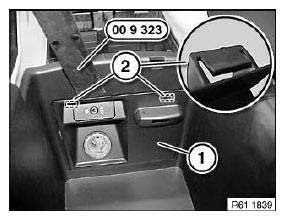
Fig. 190: Identifying Trim And Special Tool 00 9 323
Press locks (1) together and press AUX connection socket (2) out of trim (3).
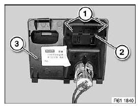
Fig. 191: Identifying Locks, AUX Connection Socket And Trim
REMOVING AND INSTALLING/REPLACING HEADPHONES CONNECTION SOCKET
Special tools required:
- 00 9 340
Unclip trim (1) with special tool 00 9 340.
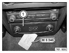
Fig. 192: Uncliping Trim With Special Tool 00 9 340
Disconnect plug connection (1).
Press locks (2) together and press switches for seat heating out of trim (3).
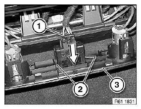
Fig. 193: Pressing Seat Heating Switches Out Of Trim
Necessary preliminary tasks:
- Remove knob for controller.
- Remove center console trim.
IMPORTANT: Risk of damage! Install knob for controller only when controller is installed.
Release screws (1).
Unclip parking brake with trim (2) towards top.
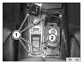
Fig. 194: Identifying Trim
Disconnect plug connection (1).
Release screws (2).
Remove parking brake button (3) from trim.
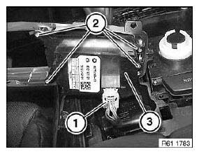
Fig. 195: Identifying Plug Connection And Parking Brake Button
REPLACING KNOB FOR CONTROLLER
Special tools required:
- 00 9 317
- 00 9 323
Engage special tools 00 9 323 and 00 9 317 as pictured.
Lever out knob for controller (1) and remove towards top.
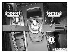
Fig. 196: Removing Knob For Controller
IMPORTANT: Risk of damage! Install knob for controller only when controller is installed.
Installation:
Fit knob for controller (1) so that guides (2) are correctly seated in mountings (3).
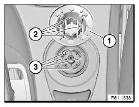
Fig. 197: Identifying Controller And Guides
REMOVING AND INSTALLING/REPLACING BUTTON UNIT (MENU/VOICE INPUT)
Necessary preliminary tasks:
- Remove center console trim.
Unclip button unit (1) at retaining points (2) and pull out.
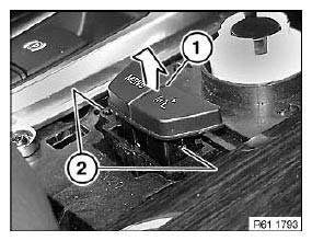
Fig. 198: Pulling Out Button Unit
Disconnect plug connection (1).
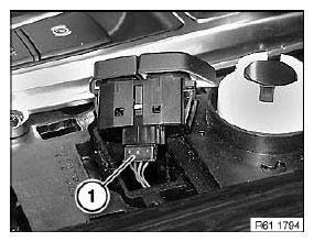
Fig. 199: Identifying Plug Connection
REMOVING AND INSTALLING (REPLACING) FRONT CONTROLLER
Necessary preliminary tasks:
- Remove center console trim.
Release screws (1).
Tightening torque.
Raise controller (2) and disconnect plug connection underneath.
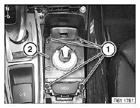
Fig. 200: Disconnecting Plug Connection
Replacement:
- Remove button unit.
- Carry out programming/coding.
REPLACING SWITCH COMBINATION FOR SEAT ADJUSTMENT
Necessary preliminary tasks:
- Remove cover from front seat.
Release screws (1).
Raise switch combination for seat adjustment (2).
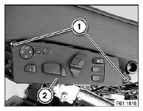
Fig. 201: Identifying Switch Combination For Seat Adjustment
Disconnect plug connection (1).
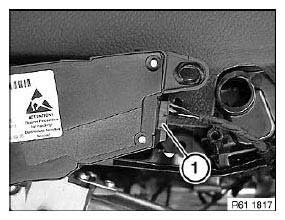
Fig. 202: Identifying Plug Connection
REMOVING AND INSTALLING/REPLACING SWITCH FOR ELECTRONIC DAMPER CONTROL (SPORT BUTTON)
Necessary preliminary tasks:
- Remove gear selector switch trim.
Release screws (1).
Raise trim (2) slightly.
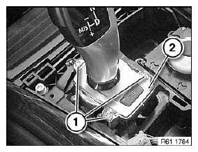
Fig. 203: Identifying Trim
Disconnect plug connection (1).
Unlock switch (2) and remove towards bottom.
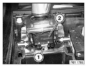
Fig. 204: Removing Switch
REMOVING AND INSTALLING/REPLACING BOTH MULTIFUNCTION STEERING WHEEL SWITCHES
Necessary preliminary tasks:
- Disconnect battery negative lead.
- Remove airbag unit.
NOTE: Illustration shows steering wheel removed.
Release screws (1).
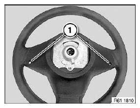
Fig. 205: Identifying Steering Wheel Screws
NOTE: Both multifunction steering wheel switches (1) are connected to each other by the wiring harness.
Disconnect plug connections (2).
Feed wiring harness (3) out of steering wheel.
Pull multifunction steering wheel switches (1) in direction of arrow out of steering wheel.
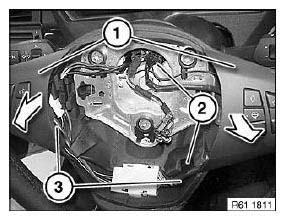
Fig. 206: Pulling Multifunction Steering Wheel Switches Out Of Steering Wheel
Installation:
Make sure electrical leads are correctly routed.
REMOVING AND INSTALLING/REPLACING BOTH SWITCHES ON SPORT STEERING WHEEL
Necessary preliminary tasks:
- Disconnect battery negative lead.
- Remove airbag unit.
NOTE: Illustration shows steering wheel removed.
Release screws (1).
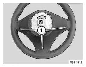
Fig. 207: Identifying Steering Wheel Screws
NOTE: Both sport steering wheel switches (1) are connected to each other by the wiring harness.
Disconnect plug connections (2).
Pull switches (1) with design cover (3) in direction of arrow out of steering wheel.
Installation:
Make sure electrical leads are correctly routed.
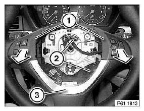
Fig. 208: Pulling Switches With Design Cover Out Of Steering Wheel
Release screws (1).
Feed wiring harness (3) out of design cover (4).
Remove switches (2) from design cover (4).
Installation:
Make sure electrical leads are correctly routed.
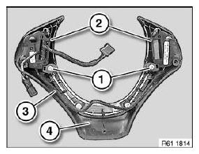
Fig. 209: Identifying Wiring Harness, Design Cover And Switches
REMOVING AND INSTALLING/REPLACING ENGINE HOOD CONTACT SWITCH
Necessary preliminary tasks:
- Remove right bonnet/hood lock.
Release screw (1).
Remove bonnet/hood contact switch (2) from bonnet/hood lock (3).
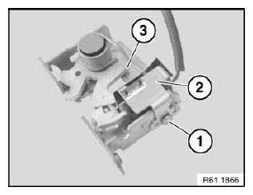
Fig. 210: Identifying Bonnet/Hood Contact Switch And Bonnet/Hood Lock
REPLACING SWITCH FOR DOOR MIRROR
Operation is described in: Replacing power window switch.
REPLACING BRAKE-LIGHT SWITCH
Necessary preliminary tasks:
- Remove trim panel for pedal assembly.
NOTE: Brake light switch (2) is situated above the brake pedal.
Disconnect plug connection (1).
Pull brake light switch (2) in direction of arrow out of brake light switch holder (3).
Press catches (4) together and unclip brake light switch holder (3) from brake pedal.
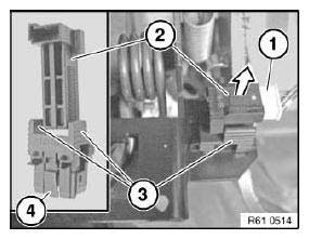
Fig. 211: Pulling Brake Light Switch Out Of Brake Light Switch Holder
Installation:
Depress brake pedal.
Slide brake light switch (2) as far as it will go into brake light switch holder (3).
Grip brake light switch holder (3), slowly return brake pedal to starting position and pull back to stop.
READ NEXT:
 Removing And Installing/Replacing Switch For Unlocking Glovebox
Necessary preliminary tasks:
Remove decorative strip from middle fresh-air grille.
Unlock catches (1).
Press switch (2) out of decorative strip.
Fig. 212: Pressing Switch Out Of Decorative Strip
Horn
REMOVING AND INSTALLING/REPLACING LEFT FANFARE HORN
Necessary preliminary tasks:
Remove front bumper trim.
Release nut (1) and feed out holder (2) with fanfare horn.
Tightening torque.
Disconnect
Insert Holder For CIGA
REMOVING AND INSTALLING/REPLACING POWER SOCKET IN STORAGE
COMPARTMENT
Necessary preliminary tasks:
Remove rear center console trim.
Unlock plug connection (1) and remove.
Press switch trim (2) out
SEE MORE:
Removing And Installing Outer Upper Rail Trim With Electric Anchor Fitting
Tensioner (From 04/2004)
Driver's seat only:
NOTE: Version with anchor fitting tensioner from 04/2004.
Lever trim (3) out of seat mechanism:
upwards,
slide towards rear
and feed out of anchor fitting tensioner.
Installation:
Secure plug connection with felt strip against unlocking.
Lock on plug connection to anchor fit
Operation via touchscreen
General information
The Control Display is equipped with a touchscreen.
You can tap on menu items and widgets. Touch
the touchscreen with your fingers. Do not use
any objects.
Opening the main menu
Tap
on the icon.
The main menu is displayed.
Adjusting widgets
The widgets can be adjusted in the
