
BMW X5: Removing And Installing/Replacing Fuel Pump (Petrol/Gasoline Vehicles)
Special tools required:
- 00 9 252
Recycling
Fuel escapes when fuel lines are detached. Have a suitable collecting container ready.
Catch and dispose of escaping fuel.
Observe country-specific waste-disposal regulations.
IMPORTANT: Ensure adequate ventilation in the place of work! Ensure absolute cleanliness when working on the open fuel tank.
Contaminants in the fuel tank can impair driving operation or may even result in vehicle breakdown!
Before starting the engine for the first time:
- Fill fuel tank with at least 5 liters of fuel
Check transfer function of suction jet pump.
Necessary preliminary tasks:
- Draw off fuel from fuel tank. See 16 00 005 Draining and Filling Fuel Tank
- Remove rear seat bench.
For vehicles with 2 seat rows only:
Disconnect plug connection (1).
Remove cover (2).
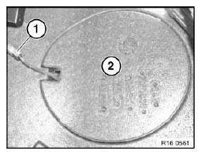
Fig. 53: Identifying Plug Connection And Cover
Release nuts (1) and remove cover for service opening (2) from right side of fuel tank.
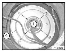
Fig. 54: Identifying Nuts And Cover For Service Opening
Disconnect plug connection (1).
Unlock quick-release fastener (2) and detach vent line.
If necessary, unlock quick-release fastener (3) for fuel feed line of independent heating and detach.
If necessary, disconnect plug connection (4) for independent heating fuel pump.
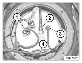
Fig. 55: Identifying Plug Connection And Quick-Release Fastener
Lever out remainder of torque break off head (1) with a screwdriver in direction of arrow.
Release hose clip of clamping ring (2) completely.
NOTE: A flexible extension can be used to release the hose clamp, e.g. special tool 00 9 252.
Press clamping ring (2) part at open end in direction of arrow and remove.
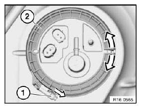
Fig. 56: Identifying Break off Head And Clamping Ring
Installation:
Make sure that service cover is installed in correct position.
Indentation (2) on clamping ring must line up with raised section (1) of tank.
Pin on service cover (3) must line up with indentation on clamping ring.
Hose clip with torque break off head (4) must always be replaced.
Tighten hose clip until torque break off head (4) breaks off.
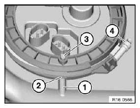
Fig. 57: Identifying Indentation, Service Cover And Break off
Installation:
Seal (1) must always be replaced.
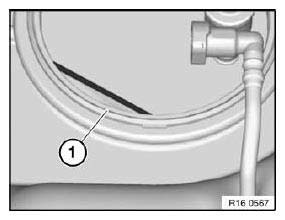
Fig. 58: Identifying Seal
Disconnect grounding cable (1) towards top.
IMPORTANT: Grounding cable (1) must be replaced if it has been detached once!
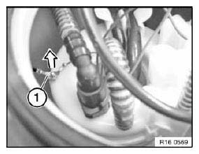
Fig. 59: Identifying Grounding Cable
Carefully raise service cover.
Unclip plastic tube (1).
Unlock and disconnect quick-connect coupling (2).
Remove fuel pump.
IMPORTANT: Catch escaping fuel in suitable container.
No fuel is permitted to get into the interior!
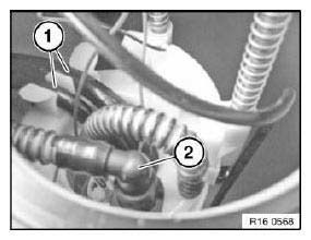
Fig. 60: Identifying Plastic Tube And Quick-Connect Coupling
With fuel pump remove, disconnect plug connection (1) and replace grounding cable (2).
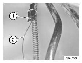
Fig. 61: Identifying Plug Connection And Grounding Cable
REMOVING AND INSTALLING/REPLACING DUST FILTER FOR TANK LEAK DIAGNOSIS MODULE (DMTL)
Necessary preliminary tasks:
- Remove rear right wheel arch trim.
Unlock and disconnect quick-connect coupling (1).
Release screws (2) and remove dust filter (3).
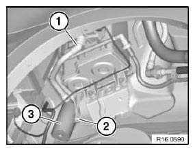
Fig. 62: Identifying Quick-Connect Coupling, Screws And Dust Filter
REMOVING AND INSTALLING OR REPLACING CONTROL UNIT FOR ELECTRIC FUEL PUMP
IMPORTANT: Read and comply with notes on protection against electrostatic damage (ESD protection).
Necessary preliminary tasks:
- Raise luggage compartment floor trim
Release screws (1) and remove battery cover towards top.
Unlock plug connections (1) and disconnect.
Release nuts (2) and remove control unit.
(Internal nut must only be slackened).
Installation:
Tightening torque 16 14 1AZ.
Replacement:
- Carry out programming/coding.
READ NEXT:
 Fuel Pump With Drive
NOTES ON FUEL PRESSURE CHECK (REFERENCE PRESSURE: ENVIRONMENT)
Feature of this version with ambient pressure:
The connection for the vacuum hose of the fuel pressure regulator is located
between the
Fuel Filter
REPLACING FUEL FILTER (M57T2)
Necessary preliminary tasks:
Switch off ignition
Remove rear assembly underside protection
Recycling:
Catch and dispose of escaping fuel.
Observe country-specific wa
SEE MORE:
Lowering/Raising Front Axle Carrier (Universal Lifter)
Special tools required:
00 2 030
31 2 255
31 2 256
31 4 170
31 5 250
31 5 255
31 5 256
WARNING: Danger to life!
Mount securing fixture for vehicle on lifting platform to prevent the
vehicle from slipping off or tilting down.
Secure engine in installation position to prevent it from falling
Lights and lighting
Switches in the vehicle
The light switch element is located next to the
steering wheel.
Night vision.
Lights off.
Daytime driving lights.
Parking lights.
Automatic headlight control.
Adaptive light functions.
Low beams.
Instrument lighting.
Right roadside parking light.
Left roadside parking ligh
