
BMW X5: Intake Manifold
REMOVING AND INSTALLING AIR INTAKE MANIFOLD (N52K)
Necessary preliminary tasks:
- Remove Tension Strut
- Remove Intake Filter Housing
- Remove Ignition Coil Cover
Open holder (2).
Disconnect plug connection (1) under of air intake manifold.
Release both crankcase breathers (3).
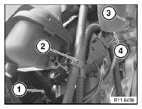
Fig. 263: Crankcase Breathers, Plug Connection And Holder
Disconnect plug connection (1).
Disconnect plug connection (3).
Release screws (4).
Detach engine wiring harness (2) from air intake manifold and lay to one side.
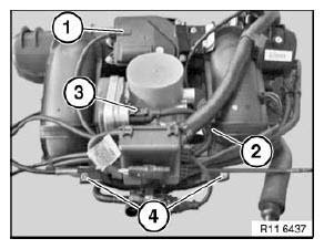
Fig. 264: Engine Wiring Harness, Screws And Plug Connections
Disconnect plug connection (1) on oil pressure switch (2).
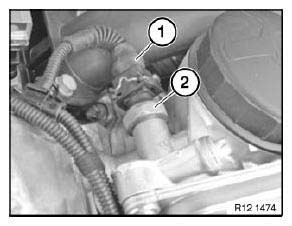
Fig. 265: Plug Connection And Oil Pressure Switch
Release fuel rail (2) and lay to one side.
NOTE: Do not detach fuel line.
Release screws (1).
For tightening torque refer to 11 61 1AZ.
Unscrew nuts (3).
For tightening torque refer to 11 61 2AZ.
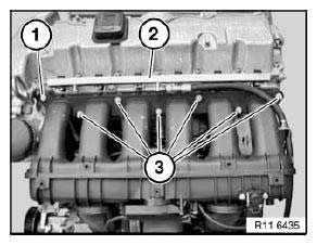
Fig. 266: Fuel Rail, Nuts And Screws
Raise air intake manifold approx. 10 cm.
Disconnect plug connections (1) at bottom.
Release tank vent line behind throttle valve assembly.
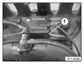
Fig. 267: Plug Connections
Installation:
Replace all seals.
Exhaust Manifold
REMOVING AND INSTALLING/REPLACING FRONT EXHAUST MANIFOLD (N52/ N52K/ N51)
Necessary preliminary tasks:
- Remove rear exhaust manifold
NOTE: The oxygen sensors are in danger of being damaged when the exhaust manifolds are removed and installed.
Remove control sensor from cylinders 1 to 3.
Remove monitor sensor from cylinders 1 to 3.
Tightening torque: 11 78 1AZ.
Unscrew nuts.
Remove exhaust manifold (1).
Installation:
Clean sealing faces and replace seals.
Replace nuts.

Fig. 268: Locating Exhaust Manifold Nuts
READ NEXT:
 Danger Of Poisoning If Oil Is Ingested/Absorbed Through The Skin
Danger of poisoning!
Ingesting oil or absorbing through the skin may cause poisoning!
Possible symptoms are:
Headaches
Dizziness
Stomach aches
Vomiting
Diarrhoea
Cramps/fits
Unconsciousness
P
SEE MORE:
Lamp Settings
TEST REQUIREMENTS FOR HEADLIGHT VERTICAL AIM ADJUSTMENT
Car parked on level ground.
Replace faulty glass and mirrors and blackened light bulbs.
Check tire pressure and correct if necessary.
Apply load equivalent to one person on driver's seat (approx. 75 kg).
Vehicle with full fuel tank or app
Removing And Installing Or Replacing Expansion Valve
WARNING: Avoid contact with refrigerant and refrigerant oil.
Follow safety instructions for handling refrigerant R 134a.
Follow safety instructions for handling refrigerant oil.
IMPORTANT: Risk of damage!
Restart engine only when A/C system has been correctly filled.
Follow instructions for openi
