
BMW X5: Removing And Installing Or Replacing Steering Column Switch Cluster
WARNING: Move wheels into straight-ahead position and do not alter this position during the repair work.
With steering wheel removed, do not under any circumstances turn/twist fixture for steering column stalk!
Necessary preliminary tasks:
- Disconnect battery negative lead.
- Remove steering wheel.
- Remove lower section of steering column trim.
- If necessary, remove switch for steering column adjustment.
WARNING: Secure volute spring cassette (1) against rotating with adhesive tape (2).
If unauthorized rotation of volute spring cassette (1) cannot be ruled out, it is essential to return volute spring cassette (1) to center position!
- Turn volute spring counterclockwise as far as it will go.
- Turn volute spring clockwise as far as it will go.
- Turn volute spring back to center position and secure so that centering pin (3) is at bottom position.
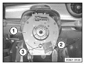
Fig. 165: Identifying Volute Spring Cassette And Centering Pin
Disconnect plug connections (1) from rear on steering column switch cluster.
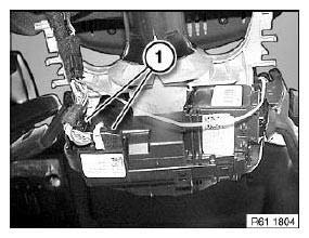
Fig. 166: Identifying Plug Connections
Release screws (1).
Remove steering column switch cluster in direction of arrow.
Installation:
NOTE: Carry out steering angle sensor adjustment.
On vehicles with active front steering, steering angle sensor adjustment is performed by means of initial operation / adjustment of active front steering.
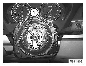
Fig. 167: Removing Steering Column Switch Cluster
Replacement:
- Remove volute spring cassette.
- Carry out programming/coding.
- Carry out steering angle sensor adjustment or adjustment for active steering.
REMOVING AND INSTALLING/REPLACING VOLUTE SPRING CASSETTE
Necessary preliminary tasks:
- Remove steering column switch cluster.
Unlock catch (1) and remove volute spring cassette (2) in direction of arrow from steering column switch cluster (3).
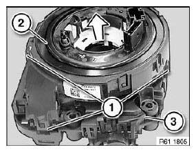
Fig. 168: Removing Volute Spring Cassette From Steering Column Switch Cluster
IMPORTANT:
- Do not turn ring (1).
- Also turning ring (1) through 360º is not permitted!
- Secure ring (1) against unauthorized turning.
Installation:
Marking (2) must line up with marking (3).
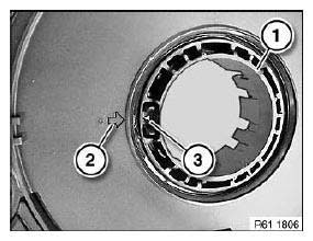
Fig. 169: Identifying Ring
Installation:
Drive pin (1) of volute spring (2) must line up correctly with opening (3) in inner ring of steering column switch cluster.
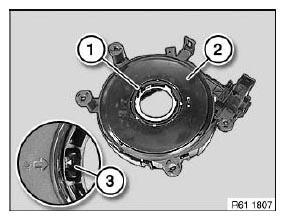
Fig. 170: Identifying Pin Of Volute Spring
REMOVING AND INSTALLING/REPLACING START/STOP SWITCH
Necessary preliminary tasks:
- Remove decorative strip on instrument panel, driver's side, on right.
Release screws (1).
Pull out Start/Stop switch (2) a little.
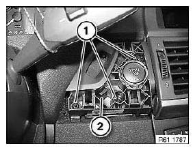
Fig. 171: Identifying Start/Stop Switch
Disconnect plug connection (1).
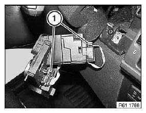
Fig. 172: Identifying Plug Connection
REMOVING AND INSTALLING/REPLACING SWITCH FOR STEERING COLUMN ADJUSTMENT
Necessary preliminary tasks:
- Remove lower section of steering column trim.
Unclip steering column adjustment switch (1) in direction of arrow.
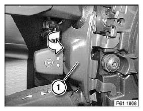
Fig. 173: Uncliping Steering Column Adjustment Switch
Disconnect plug connection (1).
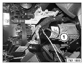
Fig. 174: Identifying Plug Connection
READ NEXT:
 Removing And Installing/Replacing Light Control Unit
Necessary preliminary tasks:
Remove left fresh-air grille.
Press out light control unit (1) from inside.
Fig. 175: Pressing Out Light Control Unit
Disconnect plug connection (1).
Remove light con
Removing And Installing/Replacing Aux Connection Socket
Special tools required:
00 9 323
Necessary preliminary tasks:
Open storage box
Unclip trim (1) with special tool 00 9 323 at retaining points (2).
Disconnect associated plug connections.
Fig.
Removing And Installing/Replacing Switch For Unlocking Glovebox
Necessary preliminary tasks:
Remove decorative strip from middle fresh-air grille.
Unlock catches (1).
Press switch (2) out of decorative strip.
Fig. 212: Pressing Switch Out Of Decorative Strip
SEE MORE:
Opening the tailgate - Comfort Access
Opening the tailgate
General information
If the tailgate is opened via Comfort Access,
locked doors are not unlocked.
To avoid locking the vehicle key in the vehicle,
do not place the vehicle key in the cargo area.
Safety information
Warning
Body parts can be jammed when operating the
tailgate. The
Replacing Level Switch For Dynamic Drive Fluid Reservoir
Unscrew nuts.
Remove shims.
Installation:
Replace self-locking nuts.
Tightening torque.
Fig. 81: Locating Dynamic Drive Fluid Reservoir Nuts
NOTE: Raise and/or turn fluid reservoir in order to gain better access
to plug
connection.
Disconnect plug connection (1).
Turn level switch (2) through ap
