
BMW X5: Socket Housing (Radio Plug), Hybrid System MQS/MPQ
Manufactured by AMP : The following contact types without strand sealing can be fitted in the plug housings:
- MQS (Micro Quadlock System)
- MPQ, width 2.8 mm (Micro Power Quadlock)
- MPQ, width 5.2 mm (Micro Power Quadlock)
Removing MPQ contacts from radio plug:
Press lock (1) in direction of arrow.
Detach secondary lock (2) from radio plug.
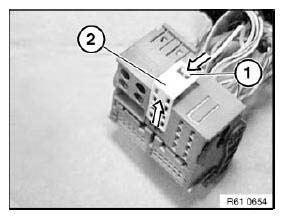
Fig. 124: Pressing Lock
Feed special tool 61 1 135 past side of contact.
Press special tool 61 1 135 in direction of arrow.
Pull wire (1) with socket contact out of radio plug (2).
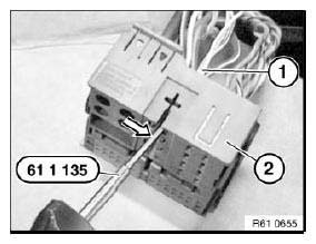
Fig. 125: Pressing Special Tool 61 1 135
Removing MQS contacts from contact carrier:
Press lock (1) in direction of arrow and pull housing (2) out of radio plug.
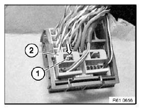
Fig. 126: Pressing Lock
Press lock (1) in direction of arrow. Pull contact carrier (2) out of housing (3).
NOTE: When the contact carrier is pulled out, the secondary locks of the socket contacts are raised.
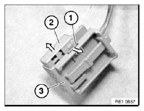
Fig. 127: Pressing Lock
Hold down retaining hook (1) of socket contact in opening of contact carrier with a small screwdriver.
Pull wire with socket contact in direction of arrow as far as secondary lock (2).
NOTE: The illustration shows an 8-pin socket housing where removal of the contacts is identical.
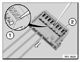
Fig. 128: Pulling Wire With Socket Contact
Hold down arrester hook in secondary lock (1) again. Pull wire with socket contact (2) out of contact carrier (3).
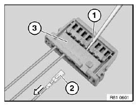
Fig. 129: Pulling Cable With Socket Contact Out Of Contact Carrier
Removing MPQ contacts from contact carrier:
Remove contact carrier (1) with MQS contacts from radio plug.
Raise lock (2) on radio plug.
Pull contact carrier (3) out of radio plug.
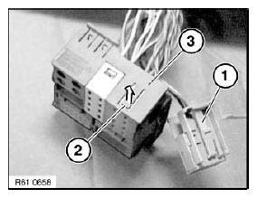
Fig. 130: Pulling Contact Carrier Out Of Radio Plug
Press lock (1) in direction of arrow.
Pull secondary lock (2) in direction of arrow completely out of contact carrier (3).
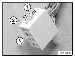
Fig. 131: Pulling Secondary Lock Out Of Contact Carrier
Press special tool 61 1 135 on inside of contact into contact carrier (2).
Pull wire with socket contact (1) out of contact carrier (2).
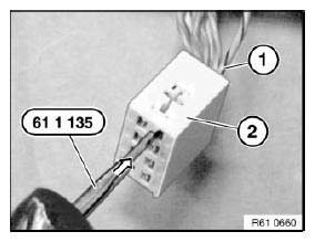
Fig. 132: Pressing Special Tool 61 1 135 On Inside Of Contact Into Contact
Carrier
TREATING CABLES AND FIBER-OPTIC CABLES
Special tools required:
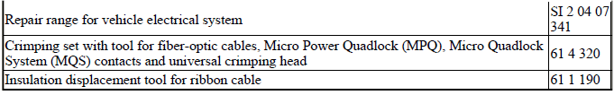
- 61 1 190
- 61 4 320
NOTE: Special tools referred to in the repair instructions below are contained in the following special tool kits:
SPECIAL TOOL KITS REFERENCE

Subject of repair instructions
- Special tools for wiring harness repairs.
- Cutting to length and stripping insulation from cables.
- Crimping stop parts (contacts).
- Butt connector for repairing a plug connection.
- Fan connector for retrofitting/repairs.
- Cutting to length and stripping insulation from optical fibers.
- Crimping optical fibers.
- Insulation displacement connector for repairing ribbon cables.
REPLACING DISTRIBUTION BOX (LUGGAGE COMPARTMENT)
WARNING: Observe safety instructions for handling vehicle battery.
Necessary preliminary tasks:
- Disconnect battery negative lead.
- Remove flap in luggage compartment panel on right.
Release expansion rivet (1).
Remove insulating mat (2).
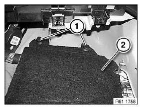
Fig. 133: Identifying Expansion Rivet And Insulating Mat
Disconnect plug connection (1).
Release bolts (2).
Disengage distribution box in direction of arrow.
Disengage emergency actuator (3).
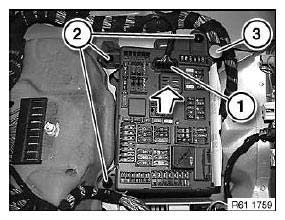
Fig. 134: Disengaging Distribution Box
Disconnect plug connection (1).
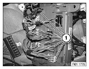
Fig. 135: Identifying Plug Connection
Disconnect plug connection (1).
Remove distribution box.
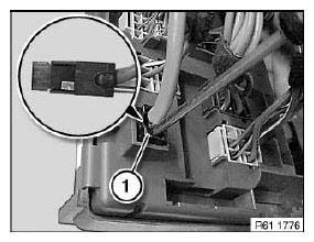
Fig. 136: Identifying Plug Connection
Replacement:
Remove fuses and relays.
REMOVING AND INSTALLING/REPLACING INTERIOR FUSE BOX
Necessary preliminary tasks:
- Remove trim for instrument panel, bottom left.
- Disconnect battery negative lead.
Release screws (1).
Remove air duct (2).
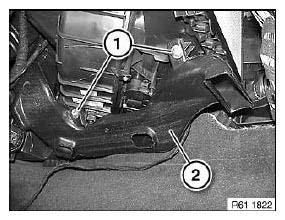
Fig. 137: Identifying Air Duct
Release screw (1).
Slacken wiring harness in cable holder (2).

Fig. 138: Identifying Cable Holder
Disconnect plug connection (1).
Release screw (2).
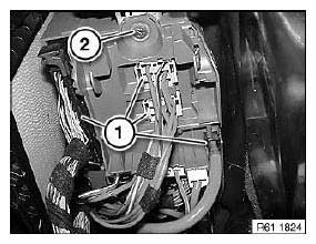
Fig. 139: Identifying Plug Connection
Lever holders (1) at bulkhead out of fuse box (2) in direction of arrow.
Lower fuse box (2).
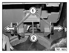
Fig. 140: Removing Holders
Disconnect plug connection (1).
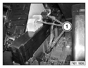
Fig. 141: Identifying Plug Connection
Turn fuse box (1) and disconnect plug connections (2).
Detach plug connections (1) on back of fuse box (2).
Replacement:
Remove fuses and relays.
Remove junction box electronics.
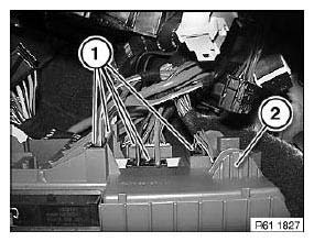
Fig. 142: Identifying Plug Connections And Fuse Box
READ NEXT:
 Distribution Box, Power
REPLACING DISTRIBUTION BOX (LUGGAGE COMPARTMENT)
WARNING: Observe safety instructions for handling vehicle battery.
Necessary preliminary tasks:
Disconnect battery negative lead.
Remove flap in lug
Instructions For Disconnecting And Connecting Battery
Observe safety instructions for handling vehicle battery.
Before disconnecting battery:
Turn off the ignition and other electrical loads/consumers to prevent
sparking when reconnecting.
NOTE: If the
SEE MORE:
Removing And Installing/Replacing Backrest Frame For Left Rear Seat (Through -
Loading System)
Necessary preliminary tasks:
Remove backrest cover.
Remove retractor mechanism.
Remove lock.
Release screws (1).
Installation:
Replace screws and insert with Loctite.
Tightening torque 52 26 07AZ.
Remove lock for centre armrest.
Fig. 160: Identifying Screw
REMOVING AND INSTALLING/REPLACING
Replacing Shaft Seal(s) For Output Shaft(s), Rear Axle Differential
Special tools required:
00 5 010
32 1 060
33 1 308
33 5 130
33 5 140
Necessary preliminary tasks:
Remove rear differential.
Withdraw shaft seal with special tools 00 5 010 and 32 1 060 / 33 1 308.
Fig. 30: Identifying Special Tools (00 5 010 ), (32 1 060) And (33 1 308)
Installing new sha
