
BMW X5: Replacing Water Valve For Heater
WARNING: Scalding hazard! Work on the cooling system may only be carried out when it has cooled down.
Follow instructions for working on cooling system!
NOTE: Disconnect coolant hoses on water valve.
Recycling
Coolant emerges when coolant lines are detached. Have a suitable collecting container ready.
Catch and dispose of escaping coolant.
Observe country-specific waste-disposal regulations.
NOTE: Engine is shown removed for purposes of clarity.
Disconnect plug connection (1).
Release hose clamps (2, 3) and detach coolant hoses.
Installation:
Do not mix up connections of coolant hoses.
Replace damaged coolant hoses.
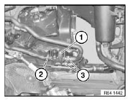
Fig. 20: Identifying Plug Connection And Hose Clamps
Installation:
To avoid the buildup of noise, make sure that the rubber mounts (1) on the water valve are securely seated in the mounting on the frame side member (2).
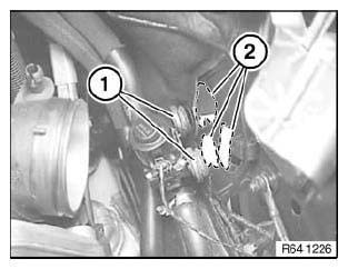
Fig. 21: Identifying Mounting On Frame Side Member
After installation:
- Fill and vent cooling system and check for leaks
REMOVING AND INSTALLING (REPLACING) CONTROL PANEL FOR HEATER - A/C SYSTEM
Necessary preliminary tasks:
- Remove middle trim for instrument panel.
Disconnect plug connection (1).
Unclip control panel (2) along dashed line from trim (3) and remove.
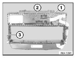
Fig. 22: Identifying Plug Connection And Control Panel
IMPORTANT: The electrical steering column adjuster must be normalized when the control panel for the heater - A/C system is programmed or replaced.
REMOVING AND INSTALLING CONTROL PANEL FOR REAR CABIN A/C SYSTEM
Necessary preliminary tasks:
- Remove rear center console trim.
Carefully unclip control panel (1) along dashed line from trim (2).
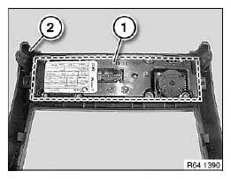
Fig. 23: Identifying Control Panel
REMOVING AND INSTALLING/REPLACING CONTROLLER FOR REAR CABIN FAN
Necessary preliminary tasks:
- Remove complete center console.
Disconnect plug connection (1).
Unlock controller (2) in counterclockwise direction and remove.
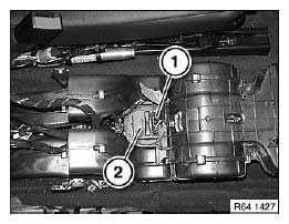
Fig. 24: Identifying Plug Connection And Controller
REMOVING AND INSTALLING/REPLACING SERVODRIVE FOR FRESH- /RECIRCULATED-AIR FLAP
Necessary preliminary tasks:
- Remove DVD changer.
Release screws (1).
Remove servomotor (2) and disconnect plug connection (3).
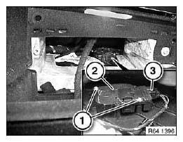
Fig. 25: Identifying Servomotor And Plug Connection
REPLACING SERVODRIVE FOR LEFT REAR CABIN BLENDING FLAP
Necessary preliminary tasks:
- Remove carrier for instrument panel.
Release screws (1) and feed out air duct (2).
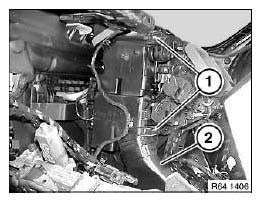
Fig. 26: Identifying Air Duct With Screws
Disconnect plug connection (1).
Release screws (2) and remove servodrive (3).
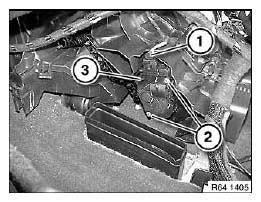
Fig. 27: Identifying Plug Connection And Servodrive With Screws
REPLACING SERVODRIVE FOR LEFT VENTILATION FLAP
Necessary preliminary tasks:
- Remove carrier for instrument panel.
Release screws (1).
Remove servomotor (2) and disconnect plug connection (3).
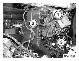
Fig. 28: Identifying Servomotor And Plug Connection
REPLACING SERVODRIVE FOR RIGHT VENTILATION FLAP
Necessary preliminary tasks:
- Remove carrier for instrument panel.
Release screws (1).
Remove servodrive (2) and disconnect plug connection (3).
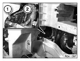
Fig. 29: Identifying Servodrive And Screws
REPLACING SERVODRIVE FOR LEFT BLENDING FLAP
Necessary preliminary tasks:
- Remove instrument panel carrier.
Release screws (1).
Remove servodrive (2) and disconnect plug connection (3).
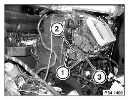
Fig. 30: Identifying Servodrive And Plug Connection
REPLACING SERVODRIVE FOR RIGHT BLENDING FLAP
Necessary preliminary tasks:
- Remove instrument panel carrier.
Release screws (1).
Remove servodrive (2) and disconnect plug connection (3).

Fig. 31: Identifying Servodrive And Plug Connection
REPLACING SERVODRIVE FOR RIGHT BLENDING FLAP
Necessary preliminary tasks:
- Remove instrument panel trim.
NOTE: For purposes of clarity, following graphics show instrument panel carrier removed.
Release screws (1).
Remove servomotor (2) and disconnect plug connection (3).
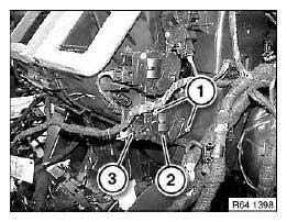
Fig. 32: Identifying Servodrive And Plug Connection
REPLACING SERVODRIVE FOR RIGHT FOOTWELL FLAP
Necessary preliminary tasks:
- Remove instrument panel trim.
Disconnect plug connection (1).
Release screws (2) and remove servodrive.
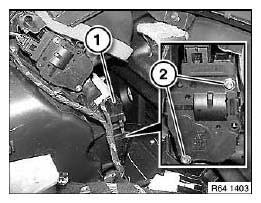
Fig. 33: Identifying Plug Connection With Screws
REPLACING ACTUATOR DRIVE OF DEFROSTING FLAPS
Necessary preliminary tasks:
- Remove instrument panel trim.
Release screws (1).
Remove servodrive (2) and disconnect plug connection (3).
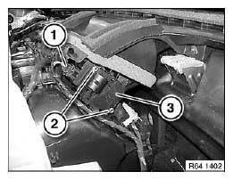
Fig. 34: Identifying Servodrive And Plug Connection
REPLACING SERVODRIVE FOR DYNAMIC PRESSURE COMPENSATION
Necessary preliminary tasks:
- Remove trim for instrument panel, bottom left.
Release screws (1) and remove air duct (2).
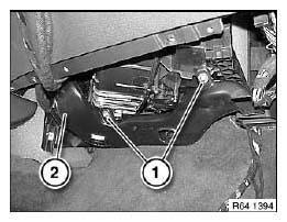
Fig. 35: Identifying Air Duct With Screws
Release screws (1).
Remove servomotor (2) and disconnect associated plug connection.
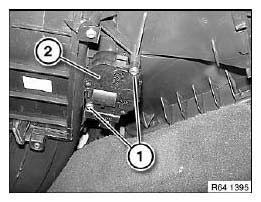
Fig. 36: Identifying Servomotor And Screws
REPLACING SERVODRIVE FOR RIGHT REAR CABIN FOOTWELL FLAP
Necessary preliminary tasks:
- Remove carrier for instrument panel.
Release screws (1).
Remove servodrive (2) and disconnect plug connection (3).
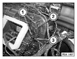
Fig. 37: Identifying Servodrive And Screws With Plug Connection
REPLACING (ONE) TEMPERATURE SENSOR FOR HEATER
Necessary preliminary tasks:
- Remove front speaker carrier
Unlock temperature sensor (1) and feed out.
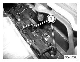
Fig. 38: Identifying Temperature Sensor
Disconnect cables (1).
Connect cables to new temperature sensor with butt connectors and heat-shrink sleeves.
Insulate cables with insulating tape.
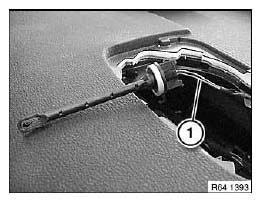
Fig. 39: Identifying Temperature Sensor Cables
REPLACING EVAPORATOR TEMPERATURE SENSOR
Necessary preliminary tasks:
- Remove panel for pedal assembly.
Pull out temperature sensor (1) and disconnect associated plug connection.
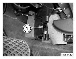
Fig. 40: Identifying Temperature Sensor
REPLACING FOGGING SENSOR
Necessary preliminary tasks:
- Remove two-part mirror base cover.
Unclip fogging sensor (1) from retaining tabs (2).
Disconnect plug connection (3).
Installation:
Make sure fogging sensor (1) is securely seated.
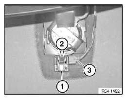
Fig. 41: Identifying Fogging Sensor And Retaining Tabs With Plug Connection
Installation:
Sensor surface (1) must be clean and free from grease.
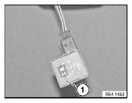
Fig. 42: Identifying Sensor
REMOVING AND INSTALLING/REPLACING SENSOR FOR AUTOMATIC RECIRCULATED AIR CONTROL
Necessary preliminary tasks:
- Remove right microfilter housing cover.
Disconnect plug connection (1).
Unlock solar sensor (2) and remove.
Fig. 43: Identifying Solar Sensor And Plug Connection
READ NEXT:
 Initializing Telestart Hand Transmitter
NOTE: The Telestart hand transmitter must be initialized when:
Hand transmitter is replaced
Car Access System control unit is replaced
The independent heating is switched on under an outside tempe
Removing And Installing Or Replacing Muffler/Silencer
WARNING: Scalding hazard!
Work on independent heating may only be carried out when it has cooled
down.
Necessary preliminary tasks:
Remove left underbody panelling.
Slacken clamp (1).
Release scre
SEE MORE:
Crimping Annular Contacts
Special tools required:
61 4 320
Crimping annular contacts:
Special tool 61 4 320
CRIMPING OPTICAL FIBERS
Special tools required:
61 4 320
To crimp optical fibers, use pliers 61 4 321 (1) in conjunction with crimping
head 61 4 323 (2) from crimping
set 61 4 320.
NOTE: Pliers (1) open automati
Hand Pump
Note: For Lifetime oil filling
SI number: 1 01 98 (294)
Order number: 00 2 080
Hand pump
Fig. 36: Identifying Hand Pump (00 2 080)
EXHAUST PIPE CUTTER
Note: For V2a pipe
Series: E12, E21, E23, E24, E28, E30, E30/C, E30tou, E31, E32, E32/3, E34,
E34tou, E36, E36/2, E36/3,
E36/5, E36/7, E36/C, E36to
