
BMW X5: Removing And Installing Or Replacing Muffler/Silencer
WARNING: Scalding hazard! Work on independent heating may only be carried out when it has cooled down.
Necessary preliminary tasks:
- Remove left underbody panelling.
Slacken clamp (1).
Release screws (2) and remove muffler (3).
Tightening torque.
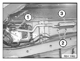
Fig. 45: Identifying Muffler/Silencer And Slacken Clamp
REMOVING AND INSTALLING/REPLACING INTAKE MUFFLER FOR INDEPENDENT/AUXILIARY HEATER
WARNING: Scalding hazard! Work on independent heating may only be carried out when it has cooled down.
Necessary preliminary tasks:
- Remove front wheel arch cover.
- Remove left underbody panelling.
Release screw (1) and unclip intake muffler (2).
Installation:
Retaining clip on intake muffler must not be damaged!
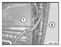
Fig. 46: Identifying Clip On Intake Muffler
Release hose clamp (1), disconnect air intake hose (2) and feed out.
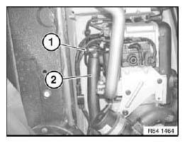
Fig. 47: Identifying Hose Clamp And Air Intake Hose
REMOVING AND INSTALLING/REPLACING COMPLETE INDEPENDENT HEATER WITH BRACKET
Special tools required:
- 13 3 010
WARNING: Scalding hazard! Work on independent heating may only be carried out when it has cooled down.
Recycling
Fuel escapes when fuel lines are detached. Have a suitable collecting container ready.
Catch and dispose of escaping fuel.
Observe country-specific waste-disposal regulations.
Necessary preliminary tasks:
- Remove left underbody panelling.
Disconnect plug connection (1).
Release hose clamp (2) and detach fuel line.
Release screw (3).
Tightening torque.
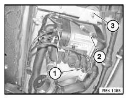
Fig. 48: Identifying Plug Connection And Hose Clamp
IMPORTANT: Secure heater (3) against falling out.
Disconnect coolant hoses (1) with special tool 13 3 010.
Release hose clamps (2) and detach coolant hoses (1).
Release nuts (4) and unclip associated hoses from holder (5).
Remove heater (3) and set down on a suitable surface.
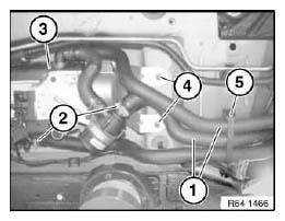
Fig. 49: Identifying Coolant Hoses, Hose Clamps And Heater
Release hose clamp (1) and remove complete heater (2) with bracket.
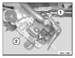
Fig. 50: Identifying Hose Clamp And Complete Heater
Replacement:
Modify muffler.
Release hose clamp (1) and detach coolant hose.
Release bolt (2).
Tightening torque.
Disconnect plug connection (3) and remove auxiliary water pump (4).
Installation:
Check coolant hoses for damage and replace if necessary.
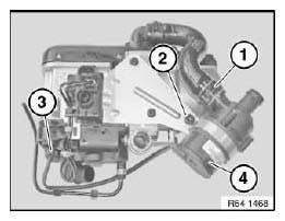
Fig. 51: Identifying Plug Connection And Auxiliary Water Pump With Bolts
Release screws (1) and remove heater from bracket (2).
Tightening torque.
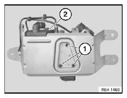
Fig. 52: Identifying Heater Bracket With Screws
After installation:
- Vent cooling system.
REPLACING AUXILIARY WATER PUMP FOR INDEPENDENT/AUXILIARY HEATER
WARNING: Scalding hazard! Work on the cooling system may only be carried out when it has cooled down.
Recycling
Coolant emerges when coolant lines are detached. Have a suitable collecting container ready.
Catch and dispose of emerging coolant.
Observe country-specific waste-disposal regulations.
Necessary preliminary tasks:
- Remove left floor assembly cover.
NOTE: Disconnect coolant hoses.
Disconnect coolant hoses (1) with special tool 13 3 010 and release associated hose clamps.
Release bolt (2).
Detach auxiliary water pump (3) and disconnect associated plug connection.
Tightening torque.
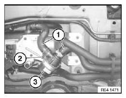
Fig. 53: Detaching Auxiliary Water Pump
After installation:
- Fill and vent cooling system and check for leaks.
READ NEXT:
 Removing And Installing Or Replacing Fuel Pump
Special tools required:
13 3 010
Necessary preliminary tasks:
Remove left underbody panelling.
Seal off water hoses at fuel pump with special tool 13 3 010
Fig. 54: Identifying Special Tool (1
Nozzles And Outlets
REMOVING AND INSTALLING/REPLACING LEFT OR RIGHT B-PILLAR AIR VENT
Necessary preliminary tasks:
Remove B-pillar trim.
Unclip retaining clip (1) and feed out air vent (2) in upward direction.
Instal
Microfilter
REPLACING MICROFILTER FOR INTERIOR VENTILATION
Necessary preliminary tasks:
Remove microfilter housing.
Unclip catches (1) and remove microfilter (2).
Installation:
Reset Condition Based Service d
SEE MORE:
Alternator With Drive And Mount
REPLACING ALTERNATOR BELT PULLEY
Special tools required:
12 7 110
Remove and install alternator drive belt.
Depending on alternator type, grip shaft with:
hexagon socket
multi-tooth socket or
Torx socket wrench
Release nut with special tool 12 7 110.
Installation:
Tightening torque, 12 31 2
Infotainment
Radio
Buttons and functions
Depending on the country and equipment version,
the radio has the following buttons.
Press: turns sound output on/
off.
Turn: adjusts the volume.
Change the entertainment
source.
Press once: changes the station/
track.
Press and hold: fast forward/
rewind the track.
