
BMW X5: Removing And Installing/Replacing Intermediate Levers (N52K)
Special tools required:
- 11 4 270
- 11 4 450
- 11 4 481
IMPORTANT: Aluminium screws/bolts must be replaced each time they are released.
The end faces of aluminium screws/bolts are painted blue for the purposes of reliable identification.
Jointing torque and angle of rotation must be observed without fail (risk of damage).
Necessary preliminary tasks:
- Remove cylinder head cover
If necessary, move eccentric shaft (1) on twin surface to minimum lift (2).
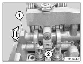
Fig. 226: Eccentric Shaft
NOTE: Oil spray nozzle must be removed from 3rd cylinder (make a note of installation position of oil spray nozzle).
Secure special tool 11 4 270 with gripping pliers (3) to guide block (2).
IMPORTANT: Special tool 11 4 270 is only secured to guide block (2).
Adjusting the gripping pliers (3) on special tool 11 4 270 is not permitted. Risk of damage!
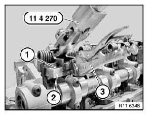
Fig. 227: Special Tool (11 4 270 ) - Gripping Pliers And Guide Block
WARNING: Risk of injury in event of incorrect use.
IMPORTANT: Improper handling. Risk of damage!
Secure both bearing pins (2) in torsion springs with knurled screw (1) of special tool 11 4 270.
Press special tool 11 4 270 in direction of arrow as far as it will go.

Fig. 228: Securing Bearing Pins In Torsion Springs With Knurled Screw
Release screw (2) of torsion spring.
Tightening torque: 11 37 2AZ.
To avoid jamming of screw (2) with torsion spring, it is necessary when releasing screw (2) to relieve the pretension on special tool 11 4 270 uniformly.
IMPORTANT: Thread on cylinder head. Risk of damage!
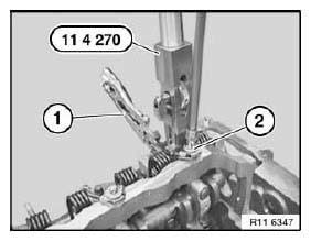
Fig. 229: Torsion Spring Screw And Special Tool (11 4 270)
Relieve tension on torsion spring (1) with special tool 11 4 270.
NOTE: Metal lug (2) cannot be disassembled and must not be removed.
Installation:
Replace torsion spring (1) if metal lug (2) is faulty.

Fig. 230: Special Tool (11 4 270), Torsion Spring And Metal Lug
Press torsion spring apart at positions (1).
Remove torsion spring towards top.
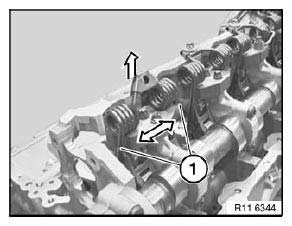
Fig. 231: Removing Torsion Spring
IMPORTANT: Uniform distribution must not be changed.
Place all components in clean and neat order in special tool 11 4 481.
All components must be reinstalled in the same positions in an engine which has already been in use.
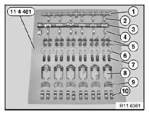
Fig. 232: Torsion Springs, Inlet Camshaft, Guide Blocks And Special Tools (11
4 481)
- Eccentric shaft with bearing
- Bearing caps of eccentric shaft (set out in order)
- Inlet camshaft
- Bearing caps of inlet camshaft (set out in order)
- Inlet valves with valve springs
- Valve plates and valve cotters
- Cam followers with HVCA elements (set out in order)
- Torsion springs
- Guide blocks (set out in order)
- Intermediate levers (set out in order)
Release screws (1) on guide block (2).
Tightening torque: 11 37 1AZ.
Place all guide blocks (2) in neat order in special tool 11 4 481.
Installation:
Mixing up the guide blocks (2) will cause the engine to suffer idle-speed fluctuations.
This will result in maladjustment of uniform distribution.
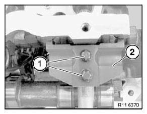
Fig. 233: Screws And Guide Block
Installation:
All contact surfaces (1) of guide block must be clean and free from oil and grease. If necessary, clean contact surfaces (1).
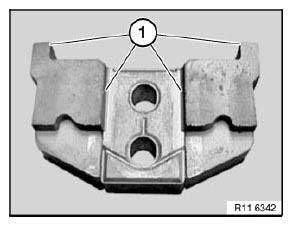
Fig. 234: Guide Block Contact Surfaces
Lift out intermediate levers (2).
Place all intermediate levers (2) in neat order in special tool 11 4 481.
Installation:
Mixing up the intermediate levers (2) will cause the engine to suffer idle-speed fluctuations.
Installation:
All contact surfaces (1) must be clean and free from oil and grease. If necessary, clean contact surfaces (1).

Fig. 235: Contact Surfaces And Intermediate Levers
All intermediate levers (1) are classified.
All intermediate levers (1) must be reinstalled in the same positions in an engine which has already been in use.
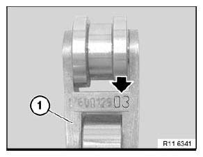
Fig. 236: Intermediate Lever Classification
IMPORTANT: Before installing intermediate levers (2), make sure cam followers are correctly positioned.
Risk of damage!
Install intermediate levers (2).
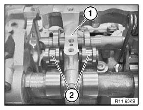
Fig. 237: Contact Surfaces And Intermediate Levers
Fit guide block (2) cleanly into opening.
Tighten screws (1) hand-tight.
Check that intermediate levers are in correct installation position.
Release screws (1) by a 1/4 turn.

Fig. 238: Screws And Guide Block
Secure special tool 11 4 450 to bolt connection (1) of eccentric shaft.
Turn eccentric lever (3) on special tool 11 4 450 in direction of arrow.
Guide block is now pretensioned.
Insert screws (2) of guide blocks.
Tightening torque: 11 37 1AZ.
Installation:
At cylinder no. 3, the guide block can be pre-installed with one screw (internal) only.
Oil spray nozzle is fitted only after torsion spring has been installed.
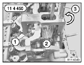
Fig. 239: Turning Eccentric Lever On Special Tool (11 4 450)
Install torsion spring (2) on guide block.
Installation:
Insert torsion spring (2) in intermediate lever (1) (see arrow).
Check that cam follower (3) is in correct installation position.
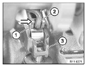
Fig. 240: Inserting Torsion Spring In Intermediate Lever
Secure special tool 11 4 270 with gripping pliers (3) to guide block (2).
IMPORTANT: Special tool 11 4 270 is only secured to guide block (2).
Adjusting the gripping pliers (3) on special tool 11 4 270 is not permitted. Risk of damage!

Fig. 241: Special Tool (11 4 270 ) - Gripping Pliers And Guide Block
WARNING: Risk of injury in event of incorrect use.
IMPORTANT: Improper handling. Risk of damage!
Secure both bearing pins (2) in torsion springs with knurled screw (1) of special tool 11 4 270.
IMPORTANT: Check torsion spring on intermediate lever to ensure correct installation position.
Press special tool 11 4 270 in direction of arrow as far as it will go.
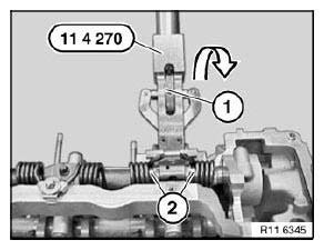
Fig. 242: Securing Bearing Pins In Torsion Springs With Knurled Screw
Insert screw (2) of torsion spring.
Tightening torque: 11 37 2AZ.
To avoid jamming of screw (2) with torsion spring, it is necessary when inserting screw (2) to increase pretension on special tool 11 4 270 uniformly.
IMPORTANT: Thread on cylinder head. Risk of damage!
Remove special tool 11 4 270.
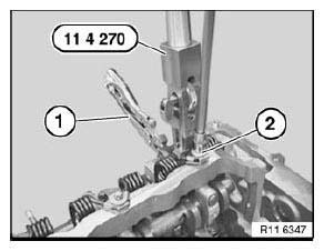
Fig. 243: Torsion Spring Screw And Special Tool (11 4 270)
At cylinder no. 3, adjust oil spray nozzle (2) so that oil spray points precisely towards spline teeth (3).
Insert screw (1) with oil spray nozzle (2) (external).
Tightening torque: 11 37 4AZ.
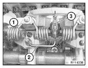
Fig. 244: Screw And Oil Spray Nozzle
Assemble engine.
READ NEXT:
 Removing And Installing/Replacing Oil Pump (N52K)
Necessary preliminary tasks:
Remove oil sump
Release screws (1).
Tightening torque: 11 41 1AZ.
Installation:
Replace aluminium screws.
Remove intake pipe (2) in direction of arrow.
Installation:
R
Removing And Installing/Replacing Chain Module For Oil Pump/Vacuum Pump
(N52K)
Special tools required:
00 9 140
11 0 290
11 0 300
11 4 120
11 4 280
11 4 360
11 4 362
11 4 440
11 5 200
11 9 280
IMPORTANT: Aluminium-magnesium materials.
No steel screws/bolts may be us
SEE MORE:
Vacuum Pump
REMOVING AND INSTALLING/REPLACING VACUUM PUMP (N62/N62TU)
NOTE: Press brake pedal several times in order to reduce vacuum
pressure in brake
booster.
Installation location:
Vacuum pump is fitted on cylinder head 1 to 4 at front on exhaust camshaft.
Remove design cover, if equipped.
Remove acoustic
Mufflers
REPLACING REAR MUFFLER (N62TU)
Special tools required:
00 2 210
31 2 220
WARNING: Scalding hazard!
Only perform these tasks after exhaust system has cooled down.
Support exhaust system with special tool 31 2 220.
Fig. 8: Identifying Special Tool (31 2 220)
NOTE: If the cutting lines are not ide
