
BMW X5: Removing And Installing/Replacing Eccentric Shaft (N52K)
Special tools required:
- 11 4 481
Necessary preliminary tasks:
- Remove cylinder head cover
- Remove intermediate lever
If necessary, move eccentric shaft (1) on twin surface to minimum lift (2).
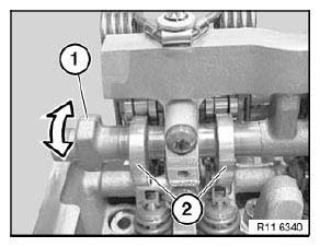
Fig. 218: Eccentric Shaft
NOTE: All bearing caps (1 and 2) of eccentric shaft are marked with numbers from 1 to 6 (1 for 1st cylinder to 6 for 6th cylinder).
Bearing cap 6 (1) is provided with a stop.
Release screws on bearing cap 6 (1).
Release screws on bearing caps 1 to 5 (2).
Set all bearing caps down in special tool 11 4 481 in a tidy and orderly fashion.
Remove eccentric shaft with gentle tilting and turning movements.

Fig. 219: Bearing Caps
IMPORTANT: Screw is not magnetic and must be secured against falling down.
Release screw.
Remove magnet wheel (1).
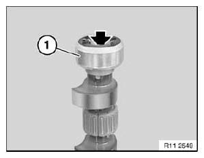
Fig. 220: Magnet Wheel
IMPORTANT: Magnet wheel (1) is highly magnetic and must be protected against metal filings/borings.
After removing, place magnet wheel (1) in a plastic bag (2) with a seal.
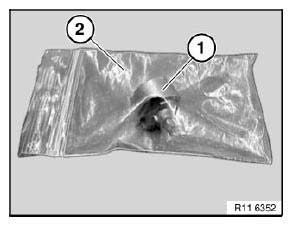
Fig. 221: Magnet Wheel And Plastic Bag
IMPORTANT: Needle bearing (1) can break very easily.
Carefully pull needle bearing (1) apart at point of separation.
Remove all needle bearings (1) from eccentric shaft.
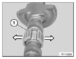
Fig. 222: Removing Needle Bearings From Eccentric Shaft
Install bearing shells (1) as pictured.
NOTE: Always replace bearing shells (1) and needle bearings together.
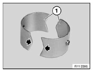
Fig. 223: Bearing Shells
Install bearing shell (1) with tip facing down (see arrow) in cylinder head.
Install bearing shell (2) with tip facing up in bearing cap.
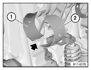
Fig. 224: Bearing Shells
NOTE: All bearing caps (1 and 2) of eccentric shaft are marked with numbers from 1 to 6 (1 for 1st cylinder to 6 for 6th cylinder).
Bearing cap 6 (1) is provided with a stop.
Insert eccentric shaft.
Adjust eccentric shaft on dihedron to minimum stroke.
Fit all bearing caps (1 and 2).
Insert all screws.
Tightening torque: 11 12 7AZ.
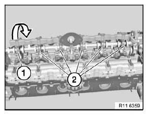
Fig. 225: Bearing Caps
Assemble engine.
READ NEXT:
 Removing And Installing/Replacing Intermediate Levers (N52K)
Special tools required:
11 4 270
11 4 450
11 4 481
IMPORTANT: Aluminium screws/bolts must be replaced each time they
are released.
The end faces of aluminium screws/bolts are painted blue for t
Removing And Installing/Replacing Oil Pump (N52K)
Necessary preliminary tasks:
Remove oil sump
Release screws (1).
Tightening torque: 11 41 1AZ.
Installation:
Replace aluminium screws.
Remove intake pipe (2) in direction of arrow.
Installation:
R
SEE MORE:
Axle Mounting
REMOVING AND INSTALLING/REPLACING FRONT COMPRESSION STRUT
IMPORTANT: Observe safety when raising the vehicle.
Driving without compression struts is not permitted!
Necessary preliminary tasks:
Remove underbody panelling (rear section).
Release screws (1).
Release screw (3).
Tightening torque.
Contents Of Body, General
General information -> Quality standard.
-> Workshop equipment.
Safety regulations -> Safety at work.
-> Information on hazards.
-> Information on vehicle protection.
Materials -> Materials science.
-> Use of materials in outer shell.
Handling electrical/electronic equipment, ai
