
BMW X5: Removing And Installing/Replacing Control Unit For Active Front Steering
IMPORTANT: Read and comply with notes on protection against electrostatic damage (ESD protection)
Necessary preliminary tasks:
- Disconnect battery negative lead.
- Remove front left wheel arch cover (rear section).
Release nut (1) and disconnect ground cable.
Disconnect plug connections (2).
Unclip cable holder (3).
Installation:
Replace damaged cable holder.
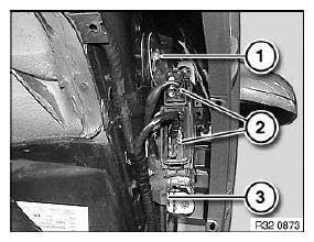
Fig. 229: Identifying Plug Connections And Cable Holder
Release nuts (1, 2).
Tightening torque.
Remove active front steering control unit (3).
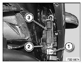
Fig. 230: Identifying Active Front Steering Control Unit
After installation:
- Replacement only: Carry out coding.
- Only when replacing / programming / coding: Carry out adjustment for active front steering.
OVERVIEW OF CONTROL UNITS
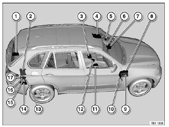
Fig. 231: Overview Of Control Units
- Distribution box (on battery)
- Distribution box (luggage compartment)
- Airbag control unit
- Roof switch centre
- Rain/light sensor
- Footwell module
- Car Access System control unit
- Junction box electronics
- Fuse box, vehicle interior
- Dynamic Drive control unit
- Control unit/module for seat adjustment
- Controller
- Control unit for comfort access system
- Rear lid module
- Trailer module
Control unit for air supply unit - Control unit, Vertical Dynamics Management
- Control unit, Park Distance Control
NOTES ON ESD PROTECTION (ELECTRO STATIC DISCHARGE)
Special tools required:
- 12 7 060
NOTE: Electrical components which are particularly sensitive to electrostatic discharge (electronic control units, sensors, etc.) are marked with the ESD warning symbol.
E -Electro
S -Static
D -Discharge
IMPORTANT: Read and comply without fail with the notes on this subject from Service Information 2 06 04 128.
Statically charged persons can discharge by touching electrical components.
NOTE: Humans can only detect a discharge starting from a level of approx. 3000 V.
The danger threshold for electrical components already starts from a level of approx. 100 V.
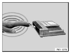
Fig. 232: Touching Electrical Components For Discharge
Example:
Mechatronic control unit.
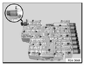
Fig. 233: Identifying Mechatronic Control Unit
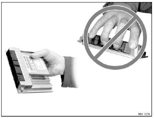
Fig. 234: Precaution For Touching Pins Or Multi-Pin Connectors Directly
IMPORTANT: Do not touch pins or multi-pin connectors directly! Touch electrical components by their housings only.
IMPORTANT: To prevent electrical components from being damaged or destroyed by electrostatic discharge, it is absolutely essential to comply with the following instructions:
- When replacing electrical components, leave the replacement components in their original packaging until immediately before they are to be installed
- If necessary, always return a removed component in its original packaging (always pack the component away immediately)
- Read and comply with user information on using the associated special tool 12 7 060
READ NEXT:
 Removing And Installing (Replacing) Trailer Module
IMPORTANT: Read and comply with notes on protection against
electrostatic damage (ESD protection).
Necessary preliminary tasks:
Remove flap in luggage compartment panel on right.
Lift back insulat
Initializing Rain/Light Sensor
NOTE: Initialization is necessary:
After replacing windshield
When installing a used rain/light sensor
NOTE:
Connect BMW diagnosis system
Initialize rain/light sensor.
REPLACING OPTICAL ELEME
Relays
RELAY CARRIER
Place special tool 61 1 153 on relay carrier (1) and carefully pull in
direction of arrow until retaining lugs (2) on
relay carrier are raised.
Fig. 257: Pulling Relay Carrier
Pull rel
SEE MORE:
Removing And Installing/Replacing Carbon Canister
Necessary preliminary tasks:
Remove rear right wheel arch trim.
Unlock quick-release fasteners (1) and disconnect vent lines.
Release screws (2) and remove carbon canister (3).
Installation:
Tightening torque 16 13 1AZ.
Fig. 27: Identifying Quick-Release Fasteners, Screws And Carbon Canister
RE
Display - BMW display key
Display
General information
The display is divided into the upper status line,
the information area, and the lower status line.
Upper status line
The upper status line displays the following information:
Vehicle secured/vehicle
unsecured.
Set time in the vehicle.
Charge state of the display
