
BMW X5: Microfilter
REPLACING MICROFILTER FOR INTERIOR VENTILATION
Necessary preliminary tasks:
- Remove microfilter housing.
Unclip catches (1) and remove microfilter (2).
Installation:
Reset Condition Based Service display according to factory specification.
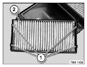
Fig. 69: Identifying Catches And Microfilter
REPLACING RECIRCULATED AIR MICROFILTER
Necessary preliminary tasks:
- Remove lower instrument panel trim.
Release screws (1) and remove air duct (2).
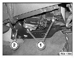
Fig. 70: Identifying Air Duct With Screws
Unclip air vent (1).
Slide lock (2) in direction of arrow and remove.
Feed out filter (3) towards bottom.
Installation:
Replacement filter consists of two halves.
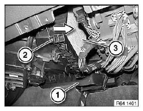
Fig. 71: Removing Filter
REMOVING AND INSTALLING OR REPLACING FRESH AIR DUCT
Necessary preliminary tasks:
- Remove microfilter housing.
Release retaining clips (1) and feed out fresh-air duct (2).
Installation:
Make sure fresh-air duct is securely seated.
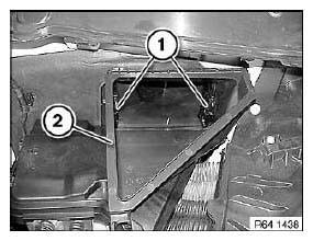
Fig. 72: Identifying Retaining Clips And Fresh-Air Duct
REMOVING AND INSTALLING/REPLACING MICROFILTER HOUSING
Necessary preliminary tasks:
- Remove right microfilter housing cover.
Disconnect plug connection (1).
Unlock rotary catches (2) and remove microfilter housing.
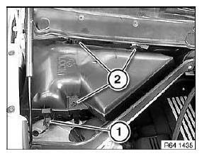
Fig. 73: Identifying Plug Connection
Replacement:
- Remove sensor for automatic recirculated air control.
- Replace microfilter.
- Reset Condition Based Service display according to factory specification.
REMOVING AND INSTALLING/REPLACING LEFT MICROFILTER HOUSING COVER
Detach mucket (1) in working area.
Unlock rotary catches (2) and remove microfilter housing cover.
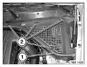
Fig. 74: Identifying Rotary Catches
REMOVING AND INSTALLING/REPLACING RIGHT MICROFILTER HOUSING COVER
Detach mucket (1) in working area.
Unlock rotary catches (2) and remove microfilter housing cover (3).
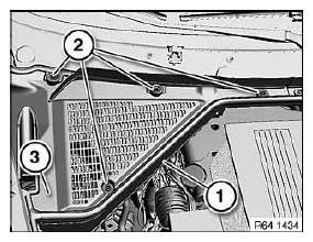
Fig. 75: Identifying Microfilter Housing Cover And Rotary Catches
READ NEXT:
 Air Conditioner Test (R 134A)
Before A/C efficiency test, satisfy following conditions:
1. Provide a MoDiC or DIS. Safeguard electrical system integrity by checking
the fault memory (no faults
in the fault memory).
2. Provide a t
Instructions For Handling Refrigerant R 134A
WARNING: Although R 134a at normal temperature is non-toxic,
non-flammable and
not explosive in air in any mixture ratio, it is still essential to follow
various safety precautions.
The filled refrig
SEE MORE:
Springs With Suspension
MEASURING RIDE-LEVEL HEIGHT OF VEHICLE
Necessary preliminary tasks:
Move vehicle into normal position.
Determine actual ride height (A) - to do so, attach tape measure to rim
flange (2) at bottom middle and measure
to lower edge of wheel arch (1).
Fig. 123: Identifying Ride Height (A)
REMOVING
Transmission Case, Oil
REMOVING AND INSTALLING/SEALING OR REPLACING TRANSMISSION SUMP
(GA6HP26Z)
IMPORTANT: Remove transmission sump only after it has cooled down.
After completion of work, check transmission oil level.
Use only the approved gear oil.
Failure to comply with this requirement will result in serious damage
