
BMW X5: Removing And Installing Or Replacing Fuel Gauge Sensor (Petrol/Gasoline, Left)
Recycling
Fuel escapes when fuel lines are detached. Have a suitable collecting container ready.
Catch and dispose of escaping fuel.
Observe country-specific waste-disposal regulations.
IMPORTANT: Ensure adequate ventilation in the place of work! Ensure absolute cleanliness when working on the open fuel tank.
Contaminants in the fuel tank can impair driving operation or may even result in vehicle breakdown!
Before starting the engine for the first time:
- Fill fuel tank with at least 5 liters of fuel
Check transfer function of suction jet pump.
Necessary preliminary tasks:
- Draw off fuel from fuel tank.
- Remove rear seat bench.
- Remove right sensor unit.
For vehicles with 2 seat rows only:
Disconnect plug connection (1).
Remove cover (2).

Fig. 43: Identifying Plug Connection And Cover
Release nuts (1) and remove cover for service opening (2) from left side of fuel tank.
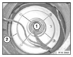
Fig. 44: Identifying Nuts And Cover For Service Opening
Disconnect plug connection (1).
Unlock quick-release fastener (2) and detach fuel feed line.
Unlock quick-release fastener (3) for vent line and detach.
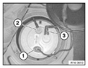
Fig. 45: Identifying Plug Connection And Quick-Release Fastener
Release completely remainder of torque break off head (1) with a screwdriver.
Remove hose clamp from clamping ring (2).
NOTE: A flexible extension can be used to release the hose clamp.
Press clamping ring (2) part at open end in direction of arrow and remove.
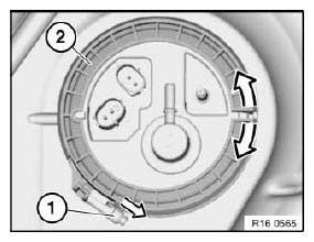
Fig. 46: Identifying Break off Head And Clamping Ring
Installation:
Make sure that service cover is installed in correct position.
Indentation (2) on clamping ring must line up with raised section (1) of tank.
Pin on service cover (3) must line up with indentation on clamping ring.
Hose clip with torque break off head (4) must always be replaced.
Tighten hose clip until torque break off head (4) breaks off.
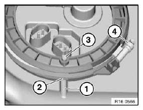
Fig. 47: Identifying Indentation, Service Cover And Break Off Head
Installation:
Seal (1) must always be replaced.
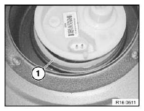
Fig. 48: Identifying Seal
Attach an auxiliary lead (1) to hose pack (2) through service opening.
The auxiliary lead is pulled through with the hose pack towards the left and facilitates subsequent reinstallation.
Installation:
Make sure when pulling through the hose pack that the tank ventilation system in the tank tunnel is not damaged.
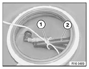
Fig. 49: Identifying Lead And Hose Pack
Remove sensor unit (1) from fuel tank.
Feed sensor unit (1) with hose pack (2) out of fuel tank.
Installation:
When replacing the sensor unit, modify the end of the auxiliary lead to the new hose pack and carefully pull in through the tank.
NOTE: Illustration shows the tank removed.
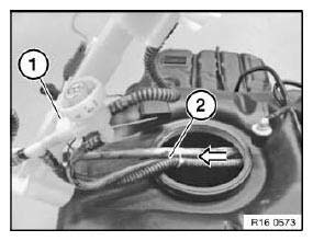
Fig. 50: Identifying Sensor Unit And Hose Pack
Unclip fuel level sensor (1) in direction of arrow from housing and then slide out of guides in direction of arrow.
Installation:
Fuel level sensor (1) must be felt and heard to snap into place.
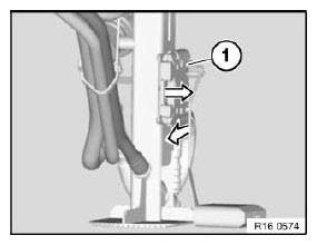
Fig. 51: Identifying Fuel Level Sensor
Disconnect plug connection (1) and disengage cable (2) from guides.
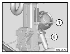
Fig. 52: Identifying Plug Connection And Disengage Cable
READ NEXT:
 Removing And Installing/Replacing Fuel Pump (Petrol/Gasoline
Vehicles)
Removing And Installing/Replacing Fuel Pump (Petrol/Gasoline
Vehicles)
Special tools required:
00 9 252
Recycling
Fuel escapes when fuel lines are detached. Have a suitable collecting
container ready.
Catch and dispose of escaping fuel.
Observe country-specific was
Fuel Pump With Drive
NOTES ON FUEL PRESSURE CHECK (REFERENCE PRESSURE: ENVIRONMENT)
Feature of this version with ambient pressure:
The connection for the vacuum hose of the fuel pressure regulator is located
between the
SEE MORE:
Checking Brakes On Test Stand
IMPORTANT: Only brake test stands (analyzers) with test speeds of 2.5 -
6 km/h may be used.
Before driving onto the brake test stand (dynamic brake analyzer), switch off
the Hill Descent Control (HDC) and keep it switched off while testing the
brakes.
The HDC indicator lamp must not light up!
NOT
Exhaust System, Complete
REMOVING AND INSTALLING COMPLETE EXHAUST SYSTEM (N52K)
Special tools required:
31 2 220 31 2 220 SUPPORT PLATE
WARNING: Scalding hazard!
Only perform this work after engine has cooled down.
Danger of injury!
Removal of the exhaust system must be carried out with the assistance of a
second person
