
BMW X5: Overview Of Heater/Air Conditioner Servomotors
BMW X5 (G05) 2019-2026 Service & Repair Manual / Heating And Air Conditioning / Heater With Operation / Overview Of Heater/Air Conditioner Servomotors
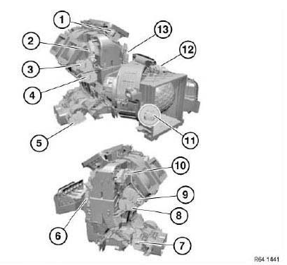
Fig. 1: Identifying Heater/Air Conditioner Servomotors Components Location
- Servomotor, defrosting
- Servomotor, footwell, rear cabin right
- Servomotor, ventilation, front right
- Servomotor, stratification, front right
- Servomotor, stratification/shut-off, rear cabin, right
- Servomotor, footwell, front left
- Servomotor, stratification, rear cabin, left/right
- Servomotor, stratification, front left/right
- Servomotor, ventilation, front left/right
- Servomotor, footwell, rear cabin, left
- Servomotor, dynamic pressure compensation
- Servomotor, fresh air/recirculated air
- Servomotor, footwell, front left/right
INSTALLING SERVODRIVE
Installation:
If necessary, align shaft of flap(s) to be actuated to position of servodrive to be installed.
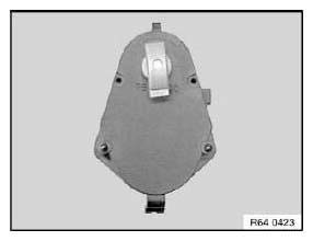
Fig. 2: Identifying Servodrive Installation Position
READ NEXT:
 Removing And Installing/Replacing Heater
WARNING: Avoid contact with refrigerant and refrigerant oil.
Follow safety instructions for handling refrigerant R 134a.
Follow safety instructions for handling refrigerant oil.
IMPORTANT: Risk of d
Removing And Installing/Replacing Heater/Air Conditioner Fan
Necessary preliminary tasks:
Disconnect battery negative lead.
Remove lower trim from instrument panel.
Release screws (1).
Fig. 10: Identifying Heater/Air Conditioner Fan Screws
Release screws
Replacing Water Valve For Heater
WARNING: Scalding hazard!
Work on the cooling system may only be carried out when it has cooled
down.
Follow instructions for working on cooling system!
NOTE: Disconnect coolant hoses on water valve.
SEE MORE:
Piezo Element
The movement of the nozzle needle in the injector is generated no longer by a
solenoid coil but rather by a
piezo-element.
A piezo-element is an electromechanical converter, i.e. it consists of a ceramic
material which converts electrical energy directly into mechanical energy
(force/travel).
Replacing Shaft Seal For Left Output Shaft
Special tools required:
31 4 160
Necessary preliminary tasks:
Remove left output shaft.
Lever shaft seal (1) out of front differential with a screwdriver (2).
Fig. 122: Identifying Shaft Seal And Screwdriver
Installing shaft seal:
NOTE: The installation protective ring (1) serves to protect t
© 2019-2026 Copyright www.bmwx5info.com
