
BMW X5: Lamp Settings
TEST REQUIREMENTS FOR HEADLIGHT VERTICAL AIM ADJUSTMENT
- Car parked on level ground.
- Replace faulty glass and mirrors and blackened light bulbs.
- Check tire pressure and correct if necessary.
- Apply load equivalent to one person on driver's seat (approx. 75 kg).
- Vehicle with full fuel tank or appropriate additional weight in luggage compartment.
- Correct adjustment of headlights in relation to engine hood (gap dimensions).
- Manual headlight vertical aim control: Turn handwheel to 0 position.
- Automatic headlight vertical aim control: Wait approx. 30 seconds after switching on lights.
- Version with xenon headlights: Wait 80 seconds after switching on lights. During this time, do not move the vehicle and avoid vibrations.
- Align headlight aimer with vehicle longitudinal axis and parallel to parking surface. Set marking line (M) on aimer to distance (e). Scale graduations on aimer are equal to a gradient in cm at a distance of 10 meters.
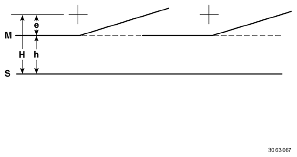
Fig. 1: Identifying Headlights Height Dimension
Light/dark limit of headlights in headlight aimer
Adjustment dimension, headlights:
- as per type plate on headlight housing in % (e.g.: 1.0 % = 10 cm / 10 m = 10 on headlight aimer).
Adjustment dimension, fog lights:
- all vehicles 2.0 % = 20 cm / 10 m = 20 on headlight aimer.
H Height of center of headlight above parking surface.
h H - e = height of marking line above parking surface
+ Central mark = center point of high-beam headlight.
M Marking line of headlamp aimer
S Parking surface of vehicle and headlight aimer
Adjustment dimension (e) is only valid for EUR. Observe differing national regulations.
ADJUSTING HEADLIGHTS
NOTE: Comply with test preconditions for headlight adjustment.
Adjust headlights at adjusting screws (1) and (2).
A definite allocation of adjusting screws is not possible.
- Adjustment screw primarily for vertical adjustment
- Adjustment screw primarily for lateral adjustment
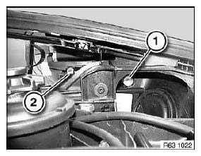
Fig. 2: Identifying Headlights Adjusting Screws
ADJUSTING FOG LAMPS
NOTE: Comply with test preconditions for headlight adjustment.
Carry out height adjustment of fog lamp (1) at adjusting screw (2).
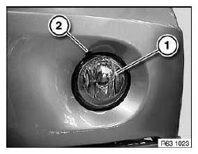
Fig. 3: Identifying Fog Lamp And Adjusting Screw
READ NEXT:
 Headlights
REMOVING AND INSTALLING/REPLACING LEFT HEADLIGHT
Operation is described in:
Removing and installing/replacing left headlight (adaptive headlight).
REMOVING AND INSTALLING/REPLACING RIGHT HEADLIGHT
Ope
Turn Signal Indicator
REMOVING AND INSTALLING/REPLACING FRONT LEFT OR RIGHT AUXILIARY
DIRECTION INDICATOR
Special tools required:
00 9 340.
WARNING: Follow instructions for handling light bulbs (exterior
lights).
Fold
Clearance And Side
REMOVING AND INSTALLING/REPLACING FRONT LEFT OR RIGHT SIDE MARKER
Special tools required:
00 9 323.
Necessary preliminary tasks:
Remove front wheel arch cover front section.
NOTE: Minimum object
SEE MORE:
Activating the voice control
system - BMW Intelligent Personal
Assistant
Activating the voice control
system
General information
There are various methods for activating the
voice control feature:
Press the button on the steering
wheel.
The microphone on the driver's side is active.
Say the wake word ›Hello BMW‹ or a personal
wake word.
The microphones on the
Search for an upgrade
Standby must be turned on to search for a software
upgrade.
Automatic search
The vehicle regularly searches for updates in the
background.
Manual search
1. "CAR".
2. "Settings".
3. "General settings".
4. "Remote Software Upgrade".
5. "Search for upgrades".
6. Follow the instructions on the Cont
