
BMW X5: Replacing Safety Pressure Switch
WARNING: Avoid contact with refrigerant and refrigerant oil.
Follow safety instructions for handling refrigerant R 134a.
Follow safety instructions for handling refrigerant oil.
IMPORTANT: Risk of damage! Restart engine only when A/C system has been correctly filled.
If A/C system is opened for more than 24 hours: Replacing drier insert for A/C system.
Necessary preliminary tasks:
- Drawing off, evacuating and filling the A/C system are not included in the time value given for this work operation.
Disconnect plug connection (1) and release safety pressure switch (2).
Installation:
Moisten sealing ring with refrigerant oil.
Tightening torque.
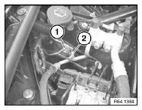
Fig. 109: Identifying Plug Connection And Pressure Switch
After installation:
- Evacuate and fill A/C system.
REMOVING AND INSTALLING OR REPLACING CONDENSER FOR A/C SYSTEM
WARNING: Avoid contact with refrigerant and refrigerant oil.
Follow safety instructions for handling refrigerant R 134a.
Follow safety instructions for handling refrigerant oil.
IMPORTANT: Risk of damage! Restart engine only when A/C system has been correctly filled.
Follow instructions for opening and replacing parts in refrigerant circuit! If A/C system is opened for more than 24 hours: Replace desiccant insert for A/C system.
Necessary preliminary tasks:
- Remove intake duct
- Remove radiator cover
- Drawing off, evacuating and filling the A/C system are not included in the time value given for this work operation.
Slacken screws (1) on both sides and pull fan cowl upwards.
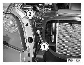
Fig. 110: Identifying Radiator Cover
Release screws (1) and pull condenser (2) up and out.
Installation:
Replace sealing rings and moisten with refrigerant oil.
Tightening torque.
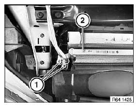
Fig. 111: Identifying Condenser And Screws
After installation:
- Evacuate and fill A/C system.
REPLACING DOUBLE PIPE
WARNING: Avoid contact with refrigerant and refrigerant oil.
Follow safety instructions for handling refrigerant R 134a.
Follow safety instructions for handling refrigerant oil.
IMPORTANT: Risk of damage! Restart engine only when A/C system has been correctly filled.
If A/C system is opened for more than 24 hours: Replacing drier insert for A/C system.
Necessary preliminary tasks:
- Drawing off, evacuating and filling the A/C system are not included in the time value given for this work operation.
Release screw (1).
Installation:
Check that rubber seal is correctly seated.
Tightening torque.
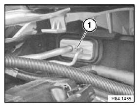
Fig. 112: Identifying Screws
Release screws (1) and remove refrigerant lines.
Remove refrigerant line from double pipe holder (2).
Installation:
Replace all sealing rings and moisten with refrigerant oil.
Tightening torque.
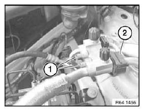
Fig. 113: Identifying Double Pipe Holder And Screws
After installation:
- Evacuate and fill A/C system.
READ NEXT:
 Instrument Cluster
REMOVING AND INSTALLING (REPLACING) INSTRUMENT CLUSTER
IMPORTANT: Read and comply with notes on protection against
electrostatic damage (ESD
protection).
NOTE:
Comply with notes and instructions o
Head-Up Display
REMOVING AND INSTALLING/REPLACING TRIM FOR HEAD-UP DISPLAY
Special tools required:
00 9 317.
Lever out trim for head-up display (1) with special tool 00 9 317 towards top.
Fig. 2: Removing Lever
I
SEE MORE:
Removing And Installing/Replacing Front Compression Strut
IMPORTANT: Observe safety when raising the vehicle.
Driving without compression struts is not permitted!
Necessary preliminary tasks:
Remove underbody panelling (rear section).
Release screws (1).
Release screw (3).
Tightening torque.
Release screw (2) and remove compression strut (4).
Secure
Removing And Installing (Replacing) Trailer Module
IMPORTANT: Read and comply with notes on protection against
electrostatic damage (ESD protection).
Necessary preliminary tasks:
Remove flap in luggage compartment panel on right.
Lift back insulating mat.
Disconnect plug connection (1).
Unlock catch (2) and remove trailer module (3) from devic
