
BMW X5: Head-Up Display
REMOVING AND INSTALLING/REPLACING TRIM FOR HEAD-UP DISPLAY
Special tools required:
- 00 9 317.
Lever out trim for head-up display (1) with special tool 00 9 317 towards top.
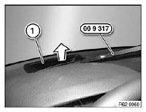
Fig. 2: Removing Lever
Installation:
Make sure detent lugs (1) are correctly seated.
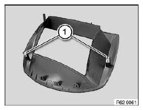
Fig. 3: Identifying Detent Lugs
REMOVING AND INSTALLING/REPLACING HEAD - UP DISPLAY
IMPORTANT: Read and comply with notes on protection against electrostatic damage (ESD protection).
IMPORTANT: Comply with notes and instructions on handling optical waveguides.
Necessary preliminary tasks:
- Remove instrument panel trim.
Remove foam seal (1) from head-up display.
Disconnect plug connection (2).
Release screws (3).
Tightening torque 62 30 2AZ. Carefully feed out head-up display towards top.
Installation:
- Clean head-up display lens.
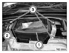
Fig. 4: Identifying Plug Connection And Seal
Replacement:
Carry out programming/coding.
ADJUSTING HEAD-UP DISPLAY
Connect vehicle to BMW diagnosis system.
Select service function under following path:
- Service function
- Body
- Display and information functions
- Head-up display
- Adjusting head-up display
NOTE: The geometric representation of the head-up display can be adjusted with the service function.
READ NEXT:
 Lamp Settings
TEST REQUIREMENTS FOR HEADLIGHT VERTICAL AIM ADJUSTMENT
Car parked on level ground.
Replace faulty glass and mirrors and blackened light bulbs.
Check tire pressure and correct if necessary.
Apply
Headlights
REMOVING AND INSTALLING/REPLACING LEFT HEADLIGHT
Operation is described in:
Removing and installing/replacing left headlight (adaptive headlight).
REMOVING AND INSTALLING/REPLACING RIGHT HEADLIGHT
Ope
SEE MORE:
Climate control rules
Principle
Depending on the equipment, some heating and
cooling functions can be automatically activated
depending on the outside temperature.
General information
The outside temperature at which the functions
are to be automatically activated can be set via
iDrive.
Activation is performed if the ou
Replacing Front Axle Carrier
WARNING: Danger to life!
Mount securing fixture for vehicle on lifting platform to prevent the
vehicle from slipping off or tilting down.
Secure engine in installation position to prevent it from falling down.
Necessary preliminary tasks:
Lower front axle support.
Remove both lower control arms
