
BMW X5: Replacing Control Unit (DME)
IMPORTANT: Read and comply with notes on protection against electrostatic damage (ESD protection).
Necessary preliminary tasks:
- Switch off ignition
- Disconnect battery negative lead.
- Remove microfilter housing.
IMPORTANT: Follow instructions for removing and installing electronic control units.
Replacement:
- Carry out programming/coding.
IMPORTANT: It is absolutely essential to read out the fault memory with the MoDiC or the BMW DIS and to create a fault memory printout.
Switch off ignition.
Lever out expander rivet.
Remove gasket (1).
Release screws (2).
Feed out partition (3) and remove.
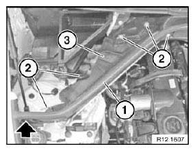
Fig. 24: Identifying Expander Rivet Gasket And Screws
Lever out expander rivet.
Release locks in direction of arrow.
Feed out fresh air duct (1) and remove.
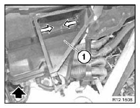
Fig. 25: Removing Fresh Air Duct
Open retainers.
Release lock (1) in direction of arrow.
Remove cover (2).
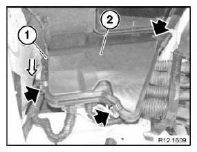
Fig. 26: Locating Retainers Lock And Cover
Release screws and remove retaining bar (1).
Unlock upper section (2) of partition seal in direction of arrow and remove.
Release grommets (3) for wiring harnesses from lower section of partition seal and from electronics box.
Installation:
Make sure grommets are correctly seated (watertightness).
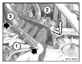
Fig. 27: Unlocking Upper Section Of Partition Seal
Unlock plugs (1) using slide in direction of arrow and remove. Remove control unit (2).
Installation:
Replacement: Note device identification number and coding.
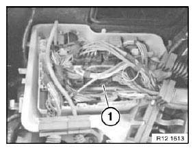
Fig. 28: Identifying DME Control Unit
NOTE: Check stored fault messages. Now clear the fault memory.
REMOVING/REPLACING KNOCK SENSORS (N52, N52K, N51)
IMPORTANT: Aluminum-magnesium materials.
No steel screws/bolts may be used due to the threat of electrochemical corrosion.
A magnesium crankcase requires aluminum screws/bolts exclusively.
Aluminum screws/bolts must be replaced each time they are released.
The end faces of aluminum screws/bolts are painted blue for the purposes of reliable identification.
Jointing torque and angle of rotation must be observed without fail (risk of damage).
Necessary preliminary tasks:
- Read out fault memory of DME control unit
- Switch off ignition
- Disconnect battery negative lead.
- Remove intake air manifold.
IMPORTANT: Mixing up the knock sensor plug connections will result in engine damage! Routing of wires and plug connections must conform to the original routing.
This eliminates the risk of confusion and mix-ups.
Release screws on both knock sensors. Remove knock sensors (1).
Installation:
Replace aluminum screws.
Tightening torque 12 14 1AZ.
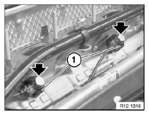
Fig. 29: Identifying Knock Sensors
Installation:
Clean support face of knock sensors on engine block.
NOTE: Check stored fault messages.
Now clear the fault memory.
CODING CONTROL MODULE (DME / DDE)
Switch off ignition.
Connect MoDiC or DIS/GT1 Tester.
Switch on ignition.
Select "Coding" program.
For subsequent procedure, follow instructions in MoDiC or DIS/GT1 Tester.
Carry out adjustment of following control units:
- EWS (electronic immobilizer)
- DME (Digital Motor Electronics) or
- DDE (Digital Diesel Electronics)
Refer to "Diagnosis and Coding" service information bulletins on subject of coding.
PROGRAMMING CONTROL UNIT (DME / DDE)
Switch off ignition.
Connect MoDiC or DIS/GT1 Tester.
Switch on ignition.
Select "Programming".
For subsequent procedure, follow instructions in MoDiC or DIS/GT1 Tester.
Carry out adjustment of following control units:
- EWS (electronic immobilizer)
- DME (Digital Motor Electronics) or
- DDE (Digital Diesel Electronics)
Refer to "Diagnosis and Coding" service information bulletins on subject of programming.
REMOVING AND INSTALLING/REPLACING ELECTRONICS BOX
IMPORTANT: Read and comply with notes on protection against electrostatic damage (ESD protection).
NOTE: Follow instructions for removing and installing electronic control
Necessary preliminary tasks:
- Read fault memory.
- Disconnect negative battery cable.
- Remove electronics box fan.
- Remove distribution box (passenger compartment).
- Release control unit holder.
Pull rubber grommets out of electronics box. Disconnect all plug connections.
Release screws (arrows).
Disconnect wiring harness on engine compartment side on right.
Remove electronics box.
Installation:
Make sure gasket (1) is correctly seated on electronics box. Add final details to vehicle.
Read fault memory.
READ NEXT:
 Alternator With Drive
REPLACING ALTERNATOR BELT PULLEY
Special tools required:
12 7 110.
Remove and install alternator drive belt.
Depending on alternator type, grip shaft with:
hexagon socket
multi-tooth socket or
Regulator
REPLACING VOLTAGE REGULATOR
Necessary preliminary tasks:
Switch off ignition.
Disconnect battery negative lead.
Notes on removing and installing electronic control units.
Remove alternator.
Bo
Starter With Mounting
REMOVING AND INSTALLING/REPLACING STARTER MOTOR (N52, N52K, N51, N53,
N54)
IMPORTANT: Aluminum-magnesium materials.
No steel screws/bolts may be used due to the threat of electrochemical
corrosion.
SEE MORE:
Removing And Installing Or Replacing Fuel Gauge Sensor (Petrol/Gasoline,
Right)
Recycling
Fuel escapes when fuel lines are detached. Have a suitable collecting
container ready.
Catch and dispose of escaping fuel.
Observe country-specific waste-disposal regulations.
IMPORTANT: Ensure adequate ventilation in the place of work!
Ensure absolute cleanliness when working on the ope
USB connection
General information
The following mobile devices can be connected
to the USB port:
Mobile phones.
Audio devices such as MP3 players.
USB storage devices.
Common file systems are supported. FAT32 and
exFAT are the recommended formats.
A connected USB device will be supplied with
charge current
