
BMW X5: Overview Of Heater/Air Conditioner Servomotors
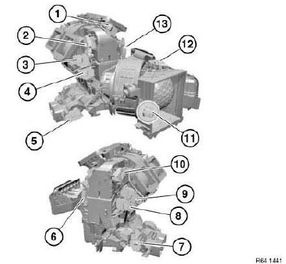
Fig. 102: Identifying Heater/Air Conditioner Servomotors Components Location
- Servomotor, defrosting
- Servomotor, footwell, rear cabin, right
- Servomotor, ventilation, front right
- Servomotor, stratification, front right
- Servomotor, stratification/shut-off, rear cabin, right
- Servomotor, footwell, front left
- Servomotor, stratification, rear cabin, left/right
- Servomotor, stratification, front left/right
- Servomotor, ventilation, front left/right
- Servomotor, footwell, rear cabin, left
- Servomotor, dynamic pressure compensation
- Servomotor, fresh air/recirculated air
- Servomotor, footwell, front left/right
INSTRUCTIONS FOR OPENING AND REPLACING PARTS IN REFRIGERANT CIRCUIT
WARNING:
- Avoid contact with refrigerant and refrigerant oil.
- Follow safety instructions for handling R 134a refrigerant.
- Follow safety instructions for handling refrigerant oil.
CAUTION:
- Always use new O-rings each time A/C connections are opened.
- Moisten O-rings with refrigerant oil prior to fitting.
- Seal all parts to be returned at openings to prevent ingress of moisture or foreign bodies.
I. Opening refrigerant circuit without part replacement, as preliminary work to further work
(e.g. engine removal):
Work sequence:
- Draw off A/C system, then determine drawn-off refrigerant oil quantity.
- Carry out main work.
- Replace removed refrigerant oil with new refrigerant oil.
- Evacuate and fill A/C system.
II. Part replacement and part replacement on account of insidious leak
(minor leak, e.g. hairline crack)
Work sequence:
- Draw off A/C system, then determine drawn-off refrigerant oil quantity.
- Carry out part replacement
- Replace removed refrigerant oil with new refrigerant oil
- Additionally replenish new refrigerant oil in accordance with replaced
parts:
- Compressor: refer to NOTES ON REPLACING COMPRESSOR
- Evaporator: 10 ml
- Condenser: 10 ml
- Desiccant insert / desiccant bottle: 30 ml
- Each replaced refrigerant line: 10 ml
- Condenser with integrated dryer: 30 ml
- Safety pressure switch and seals: no additional refrigerant oil
- Evacuate and fill A/C system.
III. Part replacement on account of sudden leak
(major leak, e.g. pipe break due to accident)
Work sequence:
- Draw off A/C system, then determine drawn-off refrigerant oil quantity.
- Carry out part replacement.
- Replace removed refrigerant oil with new refrigerant oil.
- Additionally replenish 25 ml new refrigerant oil and new refrigerant oil
in accordance with
replaced parts:
- Compressor: refer to NOTES ON REPLACING COMPRESSOR
- Evaporator: 10 ml
- Condenser: 10 ml
- Desiccant insert / desiccant bottle: 30 ml
- Each replaced refrigerant line: 10 ml
- Condenser with integrated dryer: 30 ml
- Safety pressure switch and seals: no additional refrigerant oil
- Evacuate and fill A/C system.
NOTES ON REPLACING DRIER BOTTLE OR DRIER INSERT
The drier bottle or drier insert does not have to be replaced at regular service intervals in a functioning, leakproof A/C system.
However, the drier bottle or drier insert must be replaced without fail in the event of:
- fouling of the refrigerant by filings/shavings (e.g. when the compressor is clamped)
- a leaking A/C system or loss of refrigerant
- the refrigerant circuit being opened for a period exceeding 24 hours, e.g. during repair work.
READ NEXT:
 Replacing Valve Insert For Refrigerant Line
WARNING: Avoid contact with refrigerant and refrigerant oil.
Follow safety instructions for handling refrigerant R 134a.
Follow safety instructions for handling refrigerant oil.
IMPORTANT: Risk of
Replacing Safety Pressure Switch
WARNING: Avoid contact with refrigerant and refrigerant oil.
Follow safety instructions for handling refrigerant R 134a.
Follow safety instructions for handling refrigerant oil.
IMPORTANT: Risk of da
SEE MORE:
Time
Setting the time zone
1. "CAR".
2. "Settings".
3. "General settings".
4. "Date and time".
5. "Time zone:".
6. Select the desired setting.
Setting the time
1. "CAR".
2. "Settings".
3. "General settings".
4. "Date and time".
5. "Time:".
6. Turn the Controller until the desired hours are
disp
Emission Control, Oxygen
REPLACING LEFT OXYGEN CONTROL SENSOR (N62/N62TU)
Special tools required:
11 7 030
11 9 150
(cylinder bank 5 to 8)
Necessary preliminary tasks:
Switch off ignition
Remove reinforcement plate
WARNING: Scalding hazard!
Only perform this task on an engine that has cooled down.
Unlock and detach
