
BMW X5: Leak Testing With Ultraviolet Additives (UV Additives) (BMW Leak-Testing Case)
IMPORTANT: It is absolutely essential to read and comply with the equipment manufacturer's instructions for use provided in the equipment case!
Read and comply with the instructions for use provided with the special tool particularly with regard to accident prevention, health protection and environmental protection.
Use only BMW-approved UV-additives (e.g. TRACER).
Only the basic procedure is described in the following!
WARNING: Avoid contact with refrigerant.
Follow safety precautions when handling refrigerant.
IMPORTANT: UV lamp gets very hot in the radiation area! Do not use the UV lamp without the filter glass.
Eyes and skin will suffer damage if the UV lamp is used without the filter glass.
When using the UV lamp, wear the protective goggles provided in the case.
NOTE:
- Fill the hose system of the hand pump completely with UV additive PRIOR to use
- Use the UV additive exclusively for BMW-approved refrigerant oils
- Do not operate the A/C system while the hand pump is connected or in use
- The A/C system must always be filled with an adequate amount of refrigerant to enable the leak-detecting agent to be properly distributed
Necessary preliminary tasks:
Before actually testing for leaks, check the entire refrigerant circuit using the UV leak-detecting lamp to ensure that no AV additive is already in the area of the refrigerant circuit.
If already illuminated areas are found, carefully clean the area in question with the cleaning agent contained in the case.
On initial use : Connect hand pump (1) to additive cartridge (2) and hose piece (3).
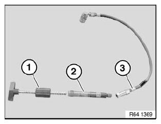
Fig. 76: Identifying Hand Pump And Additive Cartridge With Hose Piece
On initial use :
Attach vent valve (1) to quick-connect coupling (2).
Turn handle (3) on hand pump to advance the plunger until a small amount of UV additive emerges. This vents the hose system.
IMPORTANT: The entire hand pump with hose system must not be disassembled again once the filling work has been completed.
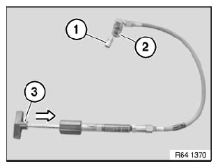
Fig. 77: Attaching Vent Valve To Quick-Connect Coupling
Attach quick-connect coupling (1) to low-pressure connection (2) of A/C system.
Turn handle on hand pump (3) until the required amount of UV additive is added.
The quantity of UV additive to be added is dependent on the amount of refrigerant in the refrigerant circuit :
- A/C systems with refrigerant filling up to 900 g: one graduation mark (4) on additive cartridge
- A/C systems with refrigerant filling in excess of 900 g: two graduation marks (4) on additive cartridge
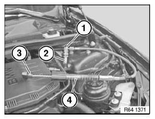
Fig. 78: Identifying Handle On Hand Pump
NOTE: After filling, remove quick-connect coupling (1) and if necessary use the cleaning agent contained in the special tool case to clean up the UV additive.
Further tasks :
- Start engine.
- Run A/C system at highest setting for 5-10 minutes in order to ensure adequate distribution of dye in the system
- Switch off engine
- Check all A/C system components for possible leaks
- Possible leaks show up in luminous green
Complete accompanying information label (1) with the relevant data and attach in an easily visible position next to the filling capacity information label (2).
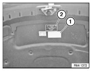
Fig. 79: Identifying Information Label
SAFETY INSTRUCTIONS FOR HANDLING REFRIGERANT R134A
WARNING: Risk of injury! Refrigerant circuit is under high pressure! Work on the refrigerant circuit may only be carried out by experts! Draw off refrigerant without fail BEFORE all repair work on the refrigerant circuit.
The refrigerant circuit is depressurized AFTER drawing off! It is absolutely essential to read and observe the relevant operating instructions for the A/C service unit used!
Protective measures/rules of conduct:
- Wear protective goggles
- Wear oil-resistant protective gloves
- Do not smoke!
- Observe country-specific safety regulations.
First aid measures:
- Eye contact: In the event of contact with the eyes, rinse immediately with plenty of running water and consult an opthalmologist.
- Skin contact: In the event of contact with skin, remove affected clothing immediately and rinse with plenty of water.
- After inhalation: If refrigerant vapors are inhaled in greater concentrations, remove the person affected to an area of fresh air and keep them under supervision. Consult a doctor. If breathing problems are experienced, breathe additional oxygen. If the person affected is breathing with difficulty or has stopped breathing, incline the person's head at the neck and administer the kiss of life.
READ NEXT:
 Drawing Off, Evacuating And Filling A/C System (R 134A)
WARNING: Refrigerant circuit is under high pressure!
Repair work may only be carried out on a DEPRESSURIZED refrigerant
circuit!
Avoid contact with refrigerant and refrigerant oil.
Follow safety inst
Instructions For Opening And Replacing Parts In Refrigerant Circuit
WARNING:
Avoid contact with refrigerant and refrigerant oil
Follow safety instructions for handling R 134a refrigerant.
Follow safety instructions for handling refrigerant oil.
CAUTION:
SEE MORE:
Removing And Installing/Replacing Dynamic Drive Control Unit
IMPORTANT: Read and comply with notes on protection against
electrostatic damage (ESD
protection).
Necessary preliminary tasks:
Disconnect battery negative lead.
Remove side cover on instrument panel.
Disconnect plug connection (1).
Release screw (2).
Tightening torque 37 14 8AZ, see 37 14 E
Speaker And Cover
REMOVING AND INSTALLING/REPLACING SPEAKER (TWEETER, FRONT DOOR)
Necessary preliminary tasks:
Remove front door trim.
Detach cover on door window frame in front area.
NOTE: For purposes of clarity, illustration shows cover removed on door
window
frame.
Remove foam wedge (1) from cover on door wi
