
BMW X5: Fuel System (N62TU)
Fuel Pump With Drive And Line
NOTES ON FUEL PRESSURE CHECK (REFERENCE PRESSURE: ENVIRONMENT)
Feature of this version with ambient pressure:
The connection for the vacuum hose of the fuel pressure regulator is located between the throttle and the air cleaner or on the air cleaner.
Test precondition:
The correct fuel pressure regulator is fitted.
- Using the EPC, check whether the fuel pressure regulator suitable for the car is fitted: Connect test adapter.
Description of operation:
The control function of the fuel pressure regulator must be guaranteed under all operating conditions. The fuel pump must always be able to generate a higher fuel pressure than the pressure regulated by the pressure regulator.
The injection rate is adjusted by means of the injection time; the injection time is controlled by the DME.
Description of operation: fuel return line
When the engine is at a standstill and the ignition key is in position 0, the fuel return line after the pressure regulator is at zero pressure.
Description of operation: pressure retaining function
The pressure regulator closes when the engine is at a standstill and the ignition key is in position 0. The fuel pressure in the delivery line is retained over an extended period. A non-return valve closes in the fuel pump.
These measures help to retain the fuel pressure in the fuel system. Extended starting times are thus avoided.
Complaint: drive characteristic faults, lack of power
- Run engine at idle speed and measure fuel pressure.
If the measured value is less than the nominal value - 0.2 bar:
- Line cross-sections in fuel feed are constricted or fuel filter is clogged, or
- Fuel pump voltage supply is not O.K.: e.g. as a result of high contact resistance (corrosion) in plug connection between wiring harness and fuel pump.
If the measured value is greater than the nominal value + 0.2 bar:
- Turn off engine stop and then observe measured value.
- If measured value drops to nominal value, then line cross-sections in fuel return are constricted or clogged.
- Check the fuel lines for kinks.
If no kinks are visible:
- Replace return lines
If measured value remains too high, then pressure regulator is in all probability faulty.
IMPORTANT: With less likelihood, the return line may be completely blocked. When the pressure regulator is removed, fuel could escape under pressure!
- Have a cleaning cloth ready and catch and dispose of escaping fuel.
- Replace the return line but not the pressure regulator.
Complaint: starting problems
- Run engine briefly at idle speed and switch off.
- Note down measured value while engine is stopped.
- Read off measured value again after approx. 20 to 30 minutes while
engine is stopped.
Special tool 13 3 010 (hose clamp) is required for the following test.
If the measured value has dropped by more than 0.5 bar:
- Start engine and wait briefly for a stable pressure increase.
- Switch off the engine and immediately pinch off the delivery line just before the pressure gauge with the special tool 13 3 010.
- Note down measured value
- Read off measured value again after approx. 20 to 30 minutes while engine is stopped
If the measured value has now dropped by less than 0.5 bar, the following faults can be present:
- Fault in delivery lines.
- Fault in in-tank delivery hose.
- Faulty pressure-holding non-return valve in fuel pump.
Check components. Replace faulty components.
If the measured value has dropped by more than 0.5 bar again:
- Replace pressure regulator
NOTE:
- All the fuel hoses and hose clips which were detached within the framework of the checks must be replaced.
- Interrogate fault memory of DME control unit. Check stored fault messages. Rectify faults. Now clear the fault memory.
CHECKING FUEL PUMP DELIVERY PRESSURE (N62TU2)
Special tools required:
- 13 5 220
- 61 3 050
Necessary preliminary tasks:
- Read out fault memory of DME control unit
- Switch off ignition
- Remove ACOUSTIC COVER and air filter housing on right
- Remove right ignition coil cover
IMPORTANT: Fuel in fuel lines is under pressure (approx. 3-5 bar)! Catch and dispose of escaping fuel.
Remove dust cap on measuring valve of fuel rail.
Unscrew non-return valve (1) on special tool kit 13 5 220.
Mount special tool kit 13 5 220 on fuel rail and tighten knurled nut until hand-tight.
Start engine.
Screw in non-return valve (1) until a pressure reading is indicated on the DIS Tester.
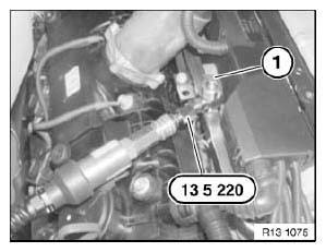
Fig. 1: Identifying Special Tool
IMPORTANT: Do not under any circumstances screw in the check valve up to the mechanical stop. This could damage the valve in the fuel rail.
Measuring fuel pressure:
- Connect pressure sensor to DIS Tester
- Start engine
- Select Measurement.
- Multimeter function appears
- Select Pressure test
- Read off fuel pressure
Test Pressure:
INJECTORS AND LINES, FUEL PRESSURE REGULATOR N62 / N45 / N46

Switch off engine.
Assemble vehicle and check fuel system for leaks.
Checking fuel pump:
Remove fuel pump relay.
Connect special tool 61 3 050 to terminal (87) and terminal (30).
Operate button and read off fuel pump delivery pressure at DIS Tester.
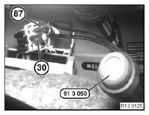
Fig. 2: Identifying Special Tool And Terminals
Notes on FUEL PRESSURE CHECK.
Installation:
Now clear the fault memory.
READ NEXT:
 Troubleshooting
CONTENTS OF ENGINE ELECTRICAL SYSTEM GENERAL
General Information -> Working on ignition system.
-> Removing and installing electronic control units.
-> Welding work (overload protection of co
Ignition Wires, Spark
REPLACING ALL SPARK PLUGS (N42, N40, N46, N45, N52, N52K, N51)
Special tools required:
12 1 171
12 1 200.
Necessary preliminary tasks:
Switch off ignition
Remove ignition coils.
Unscrew spark
SEE MORE:
Yellow lights - Indicator/warning lights
Yellow lights
Steering Assistant
The indicator light lights up
and an
acoustic signal may sound: a system interruption
is imminent.
The indicator warning light flashes: lane marking
driven over.
Additional information:
Steering and Lane Control Assistant.
Antilock Braking System ABS
The Brake Ass
Interior Lights
OVERVIEW OF INTERIOR LIGHTS
Fig. 33: Location Of Interior Lights
Glovebox light
Footwell light (footwell)
Front ceiling light
Mirror light
Interior light
Luggage compartment light
Footwell light (on floor trim panel, rear)
Footwell light (door)
REMOVING AND INSTALLING/REPLACING LEFT OR RI
