
BMW X5: Removing And Installing Right Cylinder Head (N62 From 9/03 And N62TU)
(cylinder bank 1 to 4)
NOTE: To remove the exhaust manifolds, the engine must be secured in the installation position with the special tool and then the front axle bracket lowered.
Remove right exhaust manifold.
After removing exhaust manifolds:
Reinstall front axle bracket provisionally and remove special tool for securing engine in installation position.
Open drain plug for coolant on right side of engine block.
Drain off coolant and dispose of correctly.
Installation:
Replace sealing ring.
Tightening torque of drain plug 11 11 5AZ.
Top up coolant. Vent cooling system and check for leaks.
Remove ignition coils on cylinder bank 1 to 4.
Remove servomotor for right eccentric shaft.
Remove intake air manifold.
Remove right cylinder head cover.
Remove right timing case cover.
Disconnect plug connections and lay engine wiring harness to one side.
Remove spark plugs on cylinder bank 1 to 4.
Remove vent hose on cylinder head.
NOTE: Illustration with engine removed.
Detach hose (1) on check valve (4).
Unfasten screws (2).
IMPORTANT: A spacer bushing is secured with screw (3) behind tube (5).
Release screw (3) and remove check valve (4), tube (5) and spacer bushing.
Unclip cables (6 and 7).
.png)
Fig. 71: Identifying Check Valve, Tube And Spacer Bushing
Installation:
Replace sealing ring on tube (5) and coat with antiseize agent.
Removal:
Removal of cylinder head is described separately from installation.
Remove inlet and exhaust adjustment unit on right side.
Slacken off chain tensioning piston (1) by approx. one turn.
.png)
Fig. 72: Identifying Slacken Off Chain Tensioning Piston
NOTE: Illustration with engine removed.
Remove eccentric shaft sensor (2).
.png)
Fig. 73: Locating Eccentric Shaft Sensor
Detach guide rail from cylinder head.
.png)
Fig. 74: Locating Guide Rail From Cylinder Head
Release screws between cylinder head and timing case cover.
.png)
Fig. 75: Locating Cylinder Head And Timing Case Cover With Screw
NOTE: At narrow points, use a socket with 3/8" drive and a short extension.
Release cylinder-head bolts in sequence 10... 1.
Lift off cylinder head.
Lift off cylinder head gasket.
.png)
Fig. 76: Identifying Cylinder-Head Bolts In Sequence
Remove chain tensioning piston (1).
.png)
Fig. 77: Identifying Chain Tensioning Piston
Place chain tensioning piston (1) on a level surface and compress slowly and carefully.
Repeat this procedure twice.
.png)
Fig. 78: Placing Chain Tensioning Piston On Level Surface
Installation:
Installation of cylinder head is described separately from removal.
Clean sealing faces of cylinder head and crankcase; if necessary, remove gasket debris with wooden scraper.
Make sure no gasket debris drops into the oil and coolant ducts.
Threaded bores in engine block must be free of dirt and oil (risk of cracking).
Replace sealing ring.
Install chain tensioning piston (1) and initially tighten screw connection without play.
.png)
Fig. 79: Identifying Chain Tensioning Piston
Coat joint between engine block and timing case cover with Drei Bond 1209.
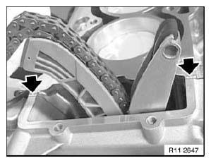
Fig. 80: Identifying Coat Joint Between Engine Block And Timing Case Cover
With Drei Bond (1209)
Check dowel sleeves (1) for damage and correct installation position.
Fit new cylinder-head seal.
.png)
Fig. 81: Identifying Dowel Sleeves
Put the cylinder head on.
NOTE: Do not wash off bolt coating. Insert new cylinder head bolts and initially tighten so that they are free of play.
At narrow points, use a socket with 3/8" drive and a short extension.
Tighten down the cylinder-head bolts in order 1... 10.
Tightening torque 11 12 8AZ.
.png)
Fig. 82: Identifying Cylinder-Head Bolts In Sequence
Insert and tighten down screws between cylinder head and timing case cover.
.png)
Fig. 83: Locating Cylinder Head And Timing Case Cover With Screw
Replacement:
Insert screw plug (1).
Installation:
Failure to install the screw (1) will result in a malfunction in the VANOS control.
.png)
Fig. 84: Identifying Screw Plug
Insert and tighten down guide rail screw.
.png)
Fig. 85: Locating Guide Rail From Cylinder Head
NOTE: Illustration with engine removed.
Install eccentric shaft sensor (2).
.png)
Fig. 86: Locating Eccentric Shaft Sensor
Tighten down chain tensioning piston (1).
Tightening torque 11 31 8AZ.
.png)
Fig. 87: Identifying Slacken Off Chain Tensioning Piston
Install inlet and exhaust adjustment units on right side.
Assemble engine.
DISASSEMBLING AND ASSEMBLING CYLINDER HEAD (N62/N62TU)
Special tools required:
- 11 9 000
- 11 9 001
- 11 9 002
- 11 9 005
- 11 9 006
- 11 9 007
- 11 9 008
- 11 9 009
- 11 9 011
- 11 9 015
Have special tool 11 9 000 ready for removing valve springs.
Secure cylinder head (1) on special tool 11 9 001.
NOTE: Secure cylinder head from above with screws contained in scope of delivery on special tool 11 9 001.
Turn special tool 11 9 001 through 180º.
.png)
Fig. 88: Identifying Cylinder Head On Special Tool (11 9 001)
Align special tool 11 9 008 in conjunction with special tool 11 9 007 on special tool 11 9 006 to relevant combustion chamber.
Place special tool 11 9 006 on cylinder head.
.png)
Fig. 89: Identifying Special Tool (11 9 008), (11 9 007) And (11 9 006)
Slide both special tools 11 9 005 in direction of arrow as far as they will go.
.png)
Fig. 90: Sliding Special Tool (11 9 005) And (11 9 006)
Turn lever of special tools 11 9 005.
Turn special tool 11 9 001 through 180º.
.png)
Fig. 91: Turning Special Tool (11 9 005) And (11 9 006)
Assemble clamping device with
- special tool 11 9 002
- special tool 11 9 009
- special tool 11 9 011
- special tool 11 9 015
.png)
Fig. 92: Identifying Special Tool (11 9 002), (11 9 009) And (11 9 015)
Remove all valve springs.
Remove all valve stem seals. Remove all valves.
REMACHINING A VALVE SEAT - CYLINDER HEAD DISASSEMBLED (N62)
Special tools required:
Special tools required:
- 00 3 520
- 00 3 580
Machine valve seat surface with special tool 00 3 520 or with 00 3 580 in accordance with tool manufacturer's instructions.
.png)
Fig. 93: Identifying Machine Valve Seat Surface With Special Tool (00 3 520)
NOTE: After machining valve-seat surface: Remachine outside and inside diameters with correction milling tool to the specified diameters until you obtain valve seat width (5).
- Valve-seat angle
- Correction angle, external diameter
- Correction angle, internal diameter
- Valve seat, external diameter
- Valve seat width
Items (1) to (5).
.png)
Fig. 94: Identifying Valve-Seat Angle, Correction Angle And External Diameter
MILLING CYLINDER HEAD SEALING FACE (N62/N62TU)
(cylinder head dismantled)
Check evenness of cylinder head sealing face with a standard straight-edge (1).
NOTE: Maximum plane deviation: longitudinal 0.10 mm.
.png)
Fig. 95: Identifying Cylinder Head Sealing Face With Standard Straight-Edge
NOTE: Maximum plane deviation: transversal 0.05 mm.
- Machining limit.
.png)
Fig. 96: Identifying Cylinder Head Maximum Plane Deviation
NOTE: A cylinder head seal 0.3 mm thicker than usual can be obtained for machined (milled) cylinder heads.
.png)
Fig. 97: Identifying Cylinder Head Seal
CHECKING CYLINDER HEAD FOR WATER LEAKS (N62/N62TU)
Special tools required:
- 11 9 430
- 11 9 431
- 11 9 432
- 11 9 433
(cylinder head dismantled)
Prepare special tool kit 11 9 430.
NOTE: Special tool kit 11 9 430 can be used for cylinder bank 1 to 4 and cylinder bank 5 to 8.
Place special tool 11 9 431 on cylinder head sealing surface, insert screws (special tool 11 9 433 ) and tighten down.
Seal coolant aperture with special tool 11 9 432 and tighten down.
.png)
Fig. 98: Identifying Special Tool (11 9 433), (11 9 431) And (11 9 432)
Connect compressed air hose (1) to pressure gauge.
Immerse cylinder head in a water bath. Inspection pressure 4.5 bar.
Check cylinder head for escaping air (cracks).
NOTE: If necessary, add cleaning agent to water bath.
.png)
Fig. 99: Identifying Cylinder Head For Escaping Air (Cracks)
READ NEXT:
 Oil Sump
REMOVING AND INSTALLING/REPLACING OIL SUMP TOP SECTION (N62/N62TU)
Special tools required:
17 0 030
REFERENCE CHART
Release screw, remove tensioner (1) from A/C compressor drive belt (E65
only).
Housing Cover
REMOVING ACOUSTIC COVER (N62/N62TU)
Unfasten screws.
Raise acoustic cover (1) and remove towards front.
Fig. 108: Identifying Acoustic Cover
REMOVING AND INSTALLING TOP LEFT TIMING CASE COVER (N62/N
Crankshaft With Bearings
REPLACING CRANKSHAFT (N62/N62TU)
REFERENCE CHART
Operation
Remove engine.
Remove cylinder head (cylinder bank 1 to 4).
Remove cylinder head (cylinder bank 5 to 8).
Remove hub for vibration damper
SEE MORE:
Intersection collision
warning
Principle
The system may prevent some accidents with
cross traffic at intersections and junctions. In the
event of an accident, the system may reduce impact
speed.
The system sounds a warning in the city speed
range before an imminent collision and activates
brakes independently, if needed.
General
Replacing Spring-Type Actuator For Active Stabilizer At Front
Special tools required:
37 1 160
WARNING: Danger of poisoning if oil is ingested/absorbed
through the skin!
Risk of injury if oil comes into contact with eyes and skin!
IMPORTANT: Adhere to the utmost cleanliness. Do not allow any dirt to
enter the hydraulic
system.
Close off pipe connections w
