
BMW X5: Removing And Installing Automatic Transmission (GA6HP26Z) N62TU
Special tools required:
- 00 2 030
- 23 0 132
- 23 4 050
- 24 1 110
- 24 2 390
- 24 4 160
- 23 4 161
- 24 4 165
IMPORTANT: After completion of work, check transmission oil level.
Use only the approved transmission fluid.
Failure to comply with this requirement will result in serious damage to the automatic transmission!
WARNING: Danger to life! Mount securing fixture for vehicle on lifting platform to prevent the vehicle from slipping off or tilting down.
Necessary preliminary tasks:
- Disconnect battery.
- If necessary, remove fan cowl.
- Remove underbody protection.
- Remove reinforcement plate.
Important notes on installation are described in this work step.
- Remove exhaust system.
- Remove heat shields
- Remove propeller shaft from front differential.
- Remove propeller shaft
- Support engine with lifter when removing transmission
Unfasten nut.
Disconnect cable (1).
Installation:
- Unfasten nut.
- Adjust cable by means of holder (2) until spacing A = 1 mm is obtained
- Tighten nut.
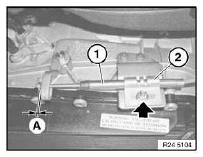
Fig. 6: Identifying Cable And Holder
Unfasten screws (1 and 2).
Tightening torque. Release lines (3) from retaining clips.
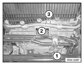
Fig. 7: Identifying Screws, Lines And Retaining Clips
Release screw (1).
Detach oil line (2) from front axle.
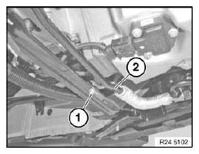
Fig. 8: Identifying Screw And Oil Line
Release screw (1).
Disconnect hydraulic lines (2) to transmission fluid cooler.
Installation:
Replace sealing rings.
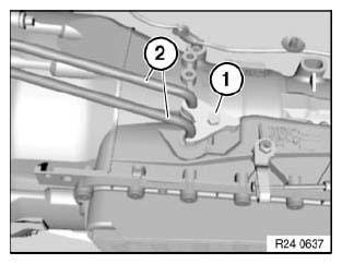
Fig. 9: Identifying Screw And Hydraulic Lines
- Unlock plug (1) by turning and disconnect
- Release cable from retainers
- Insert special tool 24 2 390 in sealing sleeve
These tasks are described in NOTES ON MECHATRONICS.
(Important: Observe important note)

Fig. 10: Identifying Plug
Release screw (1) and remove crankshaft sensor.
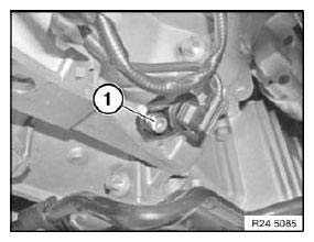
Fig. 11: Identifying Screw And Crankshaft Sensor
Release cable box (1) from holder (2).
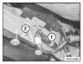
Fig. 12: Identifying Cable Box And Holder
Release connector (1) from holder and disconnect.
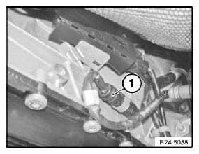
Fig. 13: Identifying Connector And Holder
Supporting transmission:
Support with special tools 23 4 050, 23 0 132 and 00 2 030.
Secure transmission with tensioning strap (1).
Tasks are described in TRANSMISSION BRACKET.
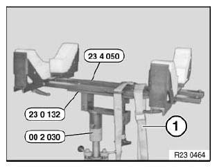
Fig. 14: Identifying Tensioning Strap And Special Tools (23 4 050, 23 0 132,
00 2 030)
Unlock and detach plugs (1) and (2).
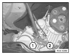
Fig. 15: Identifying Plugs
Crank engine at vibration damper in direction of rotation until screw is visible in opening.
Release all screws of torque converter with special tool 24 1 110.
Crank engine further and release remaining 3 bolts.
Tightening torque.
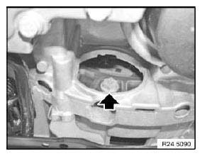
Fig. 16: Identifying Screws
Prepare special tool (1) 24 4 161 (A) with shaped section (2) 24 4 165 side (A) to (A).
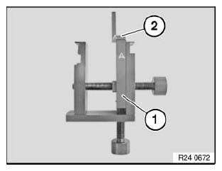
Fig. 17: Identifying Special Tool (24 4 161)
Insert special tool 24 4 160 into opening of transmission housing and tensions slightly with screw (1).
Raise by turning screw (2) and clamp down.
Then tighten down screw (1).
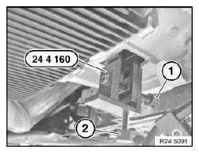
Fig. 18: Identifying Special Tool (24 4 160)
Release screws.
Tightening torque. Unflange transmission.
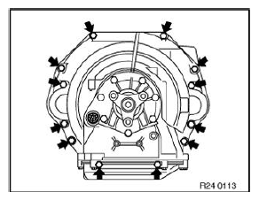
Fig. 19: Locating Screws
Installation:
Bore (1) in driving disk must be accessible from opening on engine oil pan.
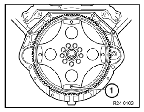
Fig. 20: Identifying Bore
Check that dowel sleeves are correctly seated.
Replace damaged dowel sleeves.
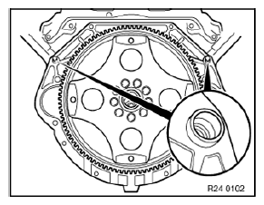
Fig. 21: Identifying Dowel Sleeves
Installation:
Rotate torque converter until bore in torque converter is flush with bore in driving disk.
Flange automatic transmission to engine.
READ NEXT:
 Installing Replacement Transmission (GA6HP26Z)
Drain automatic transmission fluid at oil drain plug.
Tightening torque.
IMPORTANT: After completion of work, program transmission control unit.
Recycling:
Catch and dispose of escaping transmission
Transmission Case, Oil
REMOVING AND INSTALLING/SEALING OR REPLACING TRANSMISSION SUMP
(GA6HP26Z)
IMPORTANT: Remove transmission sump only after it has cooled down.
After completion of work, check transmission oil level.
U
Torque Converter Bearing
REPLACING TORQUE CONVERTER SHAFT SEAL (GA6HP26Z)
Special tools required:
00 1 450
24 0 200
24 2 351
24 2 352
24 2 353
24 2 360
Necessary preliminary tasks:
Remove automatic transmission.
IM
SEE MORE:
Replacing Shaft Seal(s) For Output Shaft(s), Rear Axle Differential
Special tools required:
00 5 010
32 1 060
33 1 308
33 5 130
33 5 140
Necessary preliminary tasks:
Remove rear differential.
Withdraw shaft seal with special tools 00 5 010 and 32 1 060 / 33 1 308.
Fig. 27: Identifying Special Tools (00 5 010 ), (32 1 060) And (33 1 308)
Installing new sha
Front Side Doors
ADJUSTING DOOR
CAUTION: Do not damage adjoining body parts.
Minor corrections (realignment work) are permitted if the existing
adjustment options are not sufficient.
NOTE: Observe gap dimensions.
The door must be provided with all attachment parts for correct adjustment.
Adjust screwed body parts
