
BMW X5: Mechanical Attachments
REPLACING SELECTOR SHAFT SEAL (GA6HP26Z)
Special tools required:
- 24 5 361
- 24 5 362
- 24 5 364
- 24 5 366
IMPORTANT: After completion of work, check transmission fluid level.
Use only the approved transmission fluid. Failure to comply with this requirement will result in serious damage to the automatic transmission!
Necessary preliminary tasks:
- Remove underbody protection.
Unfasten nut.
Remove cable (1).
Installation:
Adjusting cable:
- Release nut
- Adjust cable by means of holder (2)
Distance A > or = 1 mm.
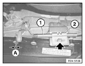
Fig. 35: Identifying Cable And Holder
Unfasten nut.
Take off holder (1).
Tightening torque.
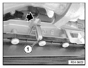
Fig. 36: Locating Nut And Holder
Screw in special tool 24 5 361 until it is firmly connected with shaft seal.
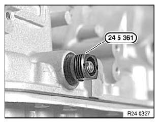
Fig. 37: Identifying Special Tool (24 5 361)
Screw special tool 24 5 362 onto special tool 24 5 361 and tighten down.
This pulls the shaft seal out of the transmission housing.
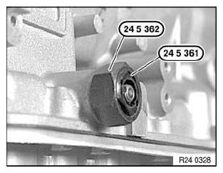
Fig. 38: Identifying Special Tool (24 5 362) And (24 5 361)
Oil sealing lip on shaft seal (1).
Screw in shaft seal (1) with special tools 24 5 366 and 24 5 364 as far as it will go.
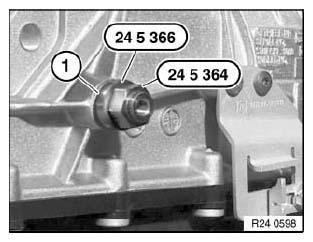
Fig. 39: Identifying Special Tools (24 5 366) And (24 5 364)
READ NEXT:
 Oil Pump
REPLACING TORQUE CONVERTER SHAFT SEAL (GA6HP26Z)
Special tools required:
00 1 450
24 0 200
24 2 351
24 2 352
24 2 353
24 2 360
Necessary preliminary tasks:
Remove automatic transmission.
IM
Regulator
MANUAL EMERGENCY RELEASE OF TRANSMISSION LOCK
In the event of a power supply interruption, e.g. flat battery or electrical
fault, the transmission lock must be
manually released, otherwise the wheel
SEE MORE:
Piezo Element
The movement of the nozzle needle in the injector is generated no longer by a
solenoid coil but rather by a
piezo-element.
A piezo-element is an electromechanical converter, i.e. it consists of a ceramic
material which converts electrical energy directly into mechanical energy
(force/travel).
Oil Cooler
FLUSHING OIL COOLER WITH LINES (AUTOMATIC TRANSMISSION)
Special tools required:
17 2 018 17 2 010 SET OF ADAPTERS
17 2 019 17 2 010 SET OF ADAPTERS
NOTE: Carry out the work steps listed when:
Fitting a new or replacement transmission
Flushing can only be carried out with the automatic transmissi
