
BMW X5: Extension Housing, Bea
REPLACING OUTPUT FLANGE SHAFT SEAL (GA6HP26Z)
Special tools required:
- 23 0 490
- 24 4 310
IMPORTANT: After completion of work, check transmission fluid level.
Use only the approved transmission fluid.
Failure to comply with this requirement will result in serious damage to the automatic transmission!
Necessary preliminary tasks:
- Remove rear underbody protection.
- Remove exhaust system.
- Remove heat shields.
- Support transmission.
- Remove transfer box.
Drive a hole into radial shaft seal (1) using a center punch.
IMPORTANT: Do not use a drill as drillings may result in transmission malfunction.
Screw special tool 23 0 490 into radial shaft seal (1).
Drive out radial shaft seal (1) with impact weight (2).
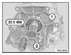
Fig. 33: Identifying Radial Shaft Seal With Special Tool (23 0 490)
Installation:
Coat sealing lips of new radial seal with clean transmission oil.
Drive shaft seal firmly home with special tool 24 4 310.
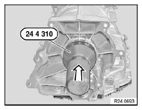
Fig. 34: Identifying Special Tool (24 4 310)
READ NEXT:
 Mechanical Attachments
REPLACING SELECTOR SHAFT SEAL (GA6HP26Z)
Special tools required:
24 5 361
24 5 362
24 5 364
24 5 366
IMPORTANT: After completion of work, check transmission fluid level.
Use only the approved t
Oil Pump
REPLACING TORQUE CONVERTER SHAFT SEAL (GA6HP26Z)
Special tools required:
00 1 450
24 0 200
24 2 351
24 2 352
24 2 353
24 2 360
Necessary preliminary tasks:
Remove automatic transmission.
IM
Regulator
MANUAL EMERGENCY RELEASE OF TRANSMISSION LOCK
In the event of a power supply interruption, e.g. flat battery or electrical
fault, the transmission lock must be
manually released, otherwise the wheel
SEE MORE:
Adaptive chassis
Principle
The adaptive suspension is an intelligent controllable
suspension.
The chassis reduces body movements with a
sporty driving style or on an uneven road.
General information
The intelligent control of the chassis increases
the driving dynamics and driving comfort depending
on the road condi
Limp-Home Mode
If a fault is diagnosed in the system, such as e.g. failure of the
high-pressure sensor, the fuel-supply control
valve is de-energized; the fuel then flows via a so-called bypass into the rail.
In the event of HPI limp-home mode, turbocharging is deactivated by an opening
of the wastegate valves.
