
BMW X5: Aerial-Antenna
REMOVING AND INSTALLING/REPLACING EMPTY HOUSING FOR ROOF-MOUNTED AERIAL/ANTENNA
Special tools required:
- 65 2 010
WARNING: Danger of injury! Special tool has sharp edges! Adapt working height to vehicle height with non-tilting and non-slip platform.
Handle special tool correctly and make sure it is positioned without tilting or slipping on the vehicle.
Risk of damage! In order to prevent dents in the roof, do not exert any pressure on the roof.
IMPORTANT: Note to customer: In order to guarantee a permanent connection and adhesive curing: After bonding the empty housing for the roof-mounted antenna, wait 24 hours before driving the vehicle through a car wash.
NOTE: Clean roof.
Mask roof (2) around empty housing for roof-mounted antenna (3) with yellow plastic adhesive tape (1). To do so, slide plastic adhesive tape under empty housing (3) slightly.
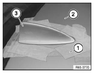
Fig. 24: Sliding Plastic Adhesive Tape Under Empty Housing
IMPORTANT: Risk of damage! Make sure your arms do not cross over (1) when holding special tool 65 2 010.
Pull handle must always be ahead of the guiding hand (2).
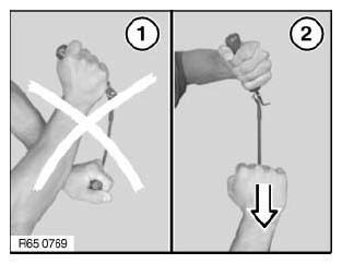
Fig. 25: Pulling Handle
Cut through adhesive bead all round with special tool 65 2 010.
Pull on handle (1) and align blade on handle (2).
NOTE: Use sharp blades only. Replace blade if necessary.
Remove empty housing for roof-mounted antenna (3).
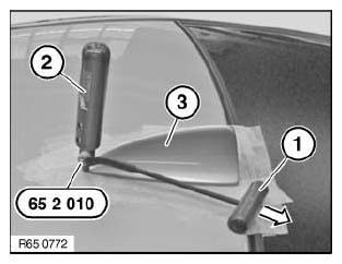
Fig. 26: Pulling On Handle And Aligning Blade On Handle
Installation
Empty housing for roof-mounted antenna is secured with window glass adhesive. All preparatory operations correspond to the Window cementing instructions.
NOTE: Replace empty housing for roof-mounted antenna is centering pins (1) on empty housing are damaged.
Bonding surface (2) must be clean and free from grease.
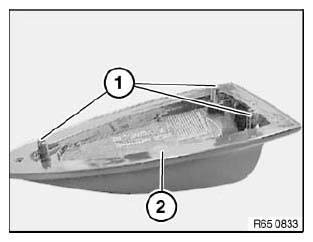
Fig. 27: Identifying Centering Pins On Empty Housing
Position two spacers (1) on cleaned empty housing.
Dimensions:
- 10 mm
- 14 mm
Position spacer (2) centrally and flush with shoulder of adhesive flange.
IMPORTANT: Use spacers without fail!
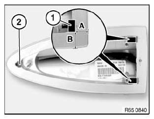
Fig. 28: Identifying Spacer Position
Apply trace of adhesive bead all round outer contour as follows.
Distance between adhesive bead and edge of aerial/antenna cover:
- 6.5 mm +- 1 mm
Start and end of bead trace must have an overlap length of max. 10 mm.
IMPORTANT: To prevent the adhesive from escaping, the adhesive bead diameter must not exceed max. 1.5 mm to 2.5 mm.
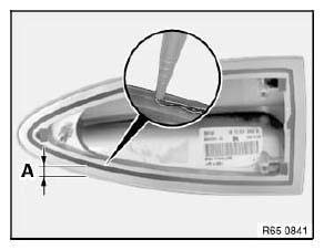
Fig. 29: Identifying Area Applying Trace Of Adhesive Bead
NOTE: Attach the empty housing coated with adhesive by hand. To spread the adhesive better, move the housing back and forth horizontally slightly when pressing down.
Secure empty housing if necessary with adhesive tape and press down uniformly.
After bonding, leave vehicle to stand for at least 3 hours at room temperature.
REMOVING AND INSTALLING/REPLACING ROOF-MOUNTED AERIAL/ANTENNA
Necessary preliminary tasks:
- Detach empty housing for roof-mounted aerial/antenna
Release screw (1) and feed out roof aerial/antenna (2) towards top.
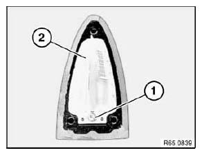
Fig. 30: Identifying Roof Aerial/Antenna
Disconnect plug connections (1) and remove aerial/antenna (2).
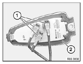
Fig. 31: Identifying Plug Connections And Aerial/Antenna
REMOVING AND INSTALLING/REPLACING ANTENNA AMPLIFIER (DIVERSITY)
Necessary preliminary tasks:
- Remove rear window frame panel.
Release screws (1).
Disconnect plug connections (2) and remove antenna amplifier.
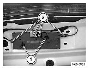
Fig. 32: Identifying Antenna Amplifier Plug Connections
REMOVING AND INSTALLING/REPLACING BACK - UP AERIAL/ANTENNA
Necessary preliminary tasks:
- Remove left luggage compartment trim panel.
Release screws (1).
Remove back-up antenna (2) and disconnect associated plug connection.
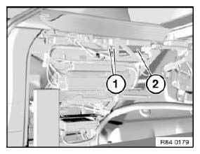
Fig. 33: Identifying Back-Up Antenna
Rear Window Aerial-Antenna
REMOVING AND INSTALLING/REPLACING BLOCKING CIRCUIT (D-PILLAR)
Necessary preliminary tasks:
- Remove rear grab handles.
- Remove both rest side sections on rear seat.
- Remove C-pillar trim panel on left and right.
- Remove panel for roof pillar at rear.
- Detach roofliner mucket in working area
- Partially detach roofliner in working area
Disconnect plug connection (1).
Unfasten screw (2) and remove blocking circuit.
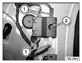
Fig. 34: Identifying Blocking Circuit Plug Connection
READ NEXT:
 Replacing Trim For Central Information Display (CID)
Necessary preliminary tasks:
Remove Central Information Display.
Carefully release catches (1).
Installation:
Catches (1) must not be damaged.
Fig. 35: Identifying Catches
Carefully raise trim (2)
Removing And Installing Rear Cabin Monitor (Complete)
Necessary preliminary tasks:
Remove fresh-air grille in rear cabin.
Remove trim from rear cabin monitor base at front.
Release screws (1) and remove rear cabin monitor with holder (2).
Disconnec
SEE MORE:
Settings
General information
Depending on the vehicle equipment and country
version, various settings for opening and closing
are possible.
These settings are stored for the driver profile
currently used.
Unlocking and locking
Doors
1. "CAR".
2. "Settings".
3. "Key button settings".
4. Select the icon.
Replacing Shaft Seal For Right Output Shaft
Special tools required:
31 4 160
Necessary preliminary tasks:
Remove right output shaft.
Lever shaft seal (1) out of bearing block with a screwdriver (2).
Fig. 125: Identifying Shaft Seal And Screwdriver
Installing shaft seal:
NOTE: The installation protective ring (1) serves to protect the
