
BMW X5: Removing And Installing/Replacing DVD Drive For Car Communication Computer (CCC)
Special tools required:
- 12 7 192
IMPORTANT: Read and comply with notes on protection against electrostatic damage (ESD protection)!
Risk of damage! Place Car Communication Computer on special tool 12 7 192 (antistatic mat) and earth/ground.
Necessary preliminary tasks:
- Partially remove CD drive for CCC.
Release screws (1) and remove cover (2) with CD drive.
Installation:
Make sure cables are correctly laid.
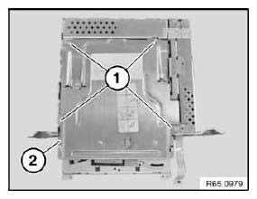
Fig. 78: Identifying CD Drive
Release screws (1).
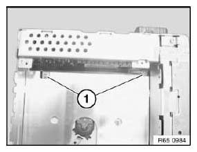
Fig. 79: Identifying CD Drive Screws
Release screws (1).
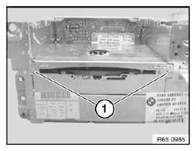
Fig. 80: Identifying CD Drive Screws
Place Car Communication Computer (2) to one side.
Feed out DVD drive and disconnect plug connections (2).
Installation:
Make sure cables are correctly laid.
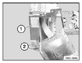
Fig. 81: Placing Car Communication Computer
REMOVING AND INSTALLING/REPLACING GYRO SENSOR DRIVE FOR CAR COMMUNICATION COMPUTER
IMPORTANT: Read and comply with notes on protection against electrostatic damage (ESD protection).
Necessary preliminary tasks:
- Remove Car Communication Computer.
If necessary, cut through warranty seal.
Release bolts (1).
Remove floor pan (2) towards bottom and set down.
IMPORTANT: Contact spring strip (3) on floor pan (2) must not be bent: otherwise risk of short-circuiting! When reinstalling floor pan (2), make sure individual springs of contact spring strip (3) are correctly seated.
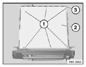
Fig. 82: Identifying Floor Pan And Spring Strip
Release bolt (1).
Detach gyro sensor for Car Communication Computer (2) in direction of arrow from plug-in contact (3).
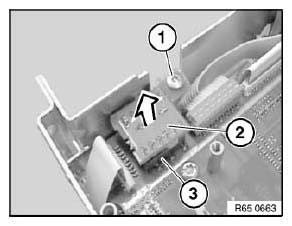
Fig. 83: Detaching Gyro Sensor For Car Communication Computer
REPLACING HIP MODULE FOR CAR COMMUNICATION COMPUTER
IMPORTANT: Read and comply with notes on protection against electrostatic damage (ESD protection).
Necessary preliminary tasks:
- Remove Car Communication Computer.
Release screws (1).
Remove cover (2) towards top.
IMPORTANT: Contact spring strip (3) on floor pan (2) must not be bent: otherwise risk of short-circuiting! When reinstalling floor pan (2), make sure individual springs of contact spring strip (3) are correctly seated.
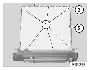
Fig. 84: Identifying Spring Strip And Floor Pan
Press catches (1) and feed out HIP module (2) in direction of arrow.
Installation:
Make sure front guides (3) of HIP module (2) are correctly seated.
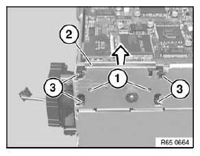
Fig. 85: Pulling HIP Module
Disconnect plug connection (1) in direction of arrow and remove HIP module (2).
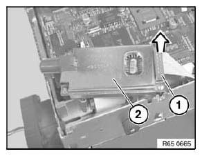
Fig. 86: Disconnecting Plug Connection
After installation:
- Cars with out-of-date software status at time of repair: After replacing the HIP module, program the Car Communication Computer. Then take the car for an initialization drive.
- Cars with current software status at time of repair: After replacing the HIP module, take the car for an initialization drive.
Initialization drive:
Drive for 15-20 minutes at 50 km/h and with good GPS reception until correct vehicle position is achieved in the navigation display.
NOTE: During this time, the position pointer of the navigation system can be motionless or move across country.
READ NEXT:
 Navigation Systems
NOTES ON HANDLING NAVIGATION COMPUTERS
All model series:
CAUTION: Risk of damage!
The navigation computer must not be disconnected from the power supply
while the LED on the computer remains lit (the
SEE MORE:
Corrosion Protection
NOTE: Following repairs, the corrosion protection work already begins
with the correct
removal of the PVC undercoating, antinoise compound and seam seals.
1.0 Removing sealing materials:
IMPORTANT:
Do not burn off PVC material with a gas burner or similar or heat
to
temperatures above 180ºC.
Adjusting Glass Slide/Tilt Sunroof Lid
Special tools required:
00 9 315 ASSEMBLY WEDGES (SET IN PLASTIC CASE)
00 9 340 DISASSEMBLY AID (2)
Necessary preliminary tasks:
Remove gaiter on left and right.
Close glass slide/tilt sunroof completely.
If the glass slide/tilt sunroof is outside the adjustment tolerances, adjust
as follo
