
BMW X5: Overview Of Sensors For Airbag System
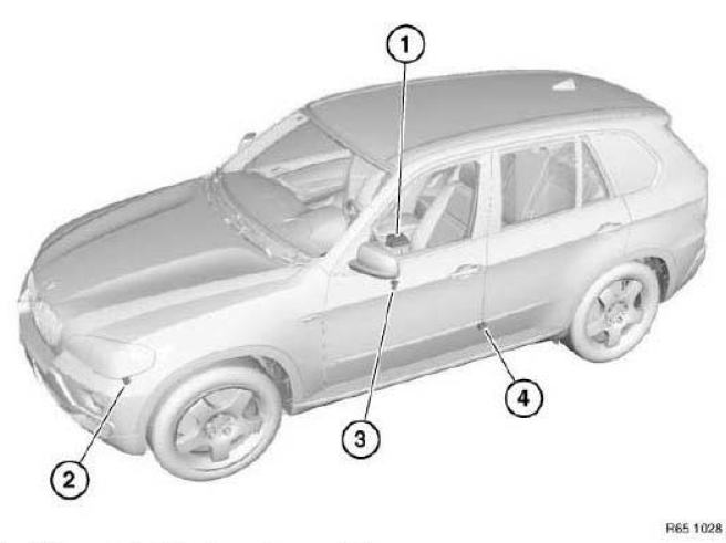
Fig. 53: Location Of Airbag System
- Airbag control unit (under centre console)
- Acceleration sensors, front (left/right)
- Sensors, front door (left/right)
- Sensors, B-pillar (left/right)
REMOVING AND INSTALLING/REPLACING AIRBAG CONTROL UNIT
IMPORTANT: Read and comply with notes on protection against electrostatic damage (ESD protection).
WARNING: Note airbag safety instructions!
Incorrect handling can activate airbag and cause injury.
Necessary preliminary tasks:
- Disconnect battery negative lead and cover.
- Remove complete center console.
- Remove rear cabin ventilation duct.
Unscrew nuts (1).
Tightening torque.
Disconnect plug connections (2).
Installation:
Make sure ground cable (2) is correctly laid.
If necessary, replace damaged cable shoe on ground cable (2).
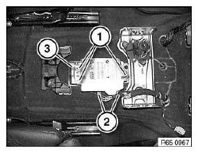
Fig. 54: Identifying Airbag Control Unit Plug Connections And Nuts
Replacement:
Carry out programming/coding. See VEHICLE PROGRAMMING AND CODING.
REMOVING AND INSTALLING/REPLACING EMERGENCY POWER SIREN WITH TILT SENSOR
Necessary preliminary tasks:
- Remove front left wheel arch trim.
Release screws (1) and remove cover (2).
Installation:
Make sure rubber grommet (3) is correctly seated.
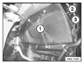
Fig. 55: Identifying Cover Screws
Release screws (1).
Remove housing (2) and disconnect associated plug connection.
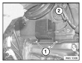
Fig. 56: Identifying Plug Connection
Replacement:
Release nut (1) and remove emergency power siren with tilt sensor (2).
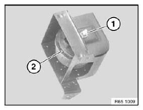
Fig. 57: Identifying Emergency Power Siren With Tilt Sensor
IMPORTANT: Risk of damage! Guides (1) of emergency power siren (2) must be correctly seated in area (3) of holder (4)!
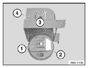
Fig. 58: Identifying Emergency Power Siren
REMOVING AND INSTALLING/REPLACING FRONT LEFT SENSOR
IMPORTANT: Read and comply with notes on protection against electrostatic damage (ESD protection).
Necessary preliminary tasks:
- Remove radiator air duct.
Release screws (1).
Remove sensor (2) and disconnect associated plug connection.
Tightening torque.
Installation:
Replace screws (1).
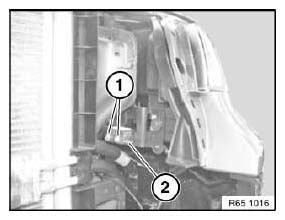
Fig. 59: Identifying Sensor
IMPORTANT: During fitting, the inscription (1) must be legible from the front.
Fig. 60: Fitting Inscription
REMOVING AND INSTALLING/REPLACING FRONT RIGHT SENSOR
Operation is identical to: See REMOVING AND INSTALLING/REPLACING FRONT LEFT SENSOR.
REMOVING AND INSTALLING (REPLACING) LEFT B-PILLAR SENSOR
WARNING: Note airbag safety instructions! Incorrect handling can activate airbag and cause injury.
Necessary preliminary tasks:
- Disconnect battery negative lead and cover.
- Remove front entrance cover strip.
- Remove seat belt retractor with holder.
Version with rear cabin air conditioning:
- Remove front seat
- Remove rear cabin ventilation duct from B-pillar
- Partially detach carpet in area of B-pillar
- If necessary, remove rear cabin ventilation duct under carpet
Release screws (1), feed out sensor and disconnect associated plug connection.
Tightening torque.
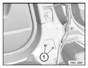
Fig. 61: Identifying B-Pillar Sensor Screw
Installation:
Establish correct positioning of B-pillar sensor (1) by means of guide pin (2) and screw (3).
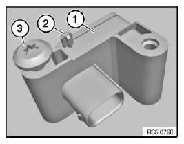
Fig. 62: Identifying B-Pillar Sensor And Guide Pin With Screw
REMOVING AND INSTALLING (REPLACING) LEFT FRONT DOOR SENSOR
WARNING: Note airbag safety instructions! Incorrect handling can activate airbag and cause injury.
Necessary preliminary tasks:
- Partially detach sound insulation.
Release screw (1).
Tightening torque. Remove sensor with pin (2) from door panel fit (3) towards rear and disconnect associated plug connection.
Installation:
Make sure fit (2) is correctly seated.
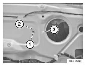
Fig. 63: Identifying Sensor With Pin From Door Panel
REMOVING AND INSTALLING/REPLACING RIGHT FRONT DOOR SENSOR
This operation is described in REMOVING AND INSTALLING (REPLACING) LEFT FRONT DOOR SENSOR.
READ NEXT:
 Overview Of Airbag Modules, Airbag Control Unit, Belt Tensioners
Fig. 64: Location Of Airbag Modules
Safety battery terminal
Side airbag, front seat, left/right
Belt tensioner, front left/right
Airbag unit, passenger side
Airbag module, drivers side
Hea
Removing And Installing/Replacing Car Communication Computer
IMPORTANT: Read and comply with notes on protection against
electrostatic damage (ESD
protection).
NOTE: Comply with notes and instructions on handling optical
waveguides.
Necessary preliminary task
SEE MORE:
Starter Lead
REMOVING AND INSTALLING OR REPLACING BATTERY POSITIVE LEAD
(BETWEEN STARTER, ALTERNATOR AND BATTERY POSITIVE TERMINAL)
Necessary preliminary tasks:
Read out fault memory of DME control unit; if necessary, work through
test schedules.
Switch off ignition.
Disconnect battery negative lead.
Rem
Unlocking And Disconnecting Different Plug Connections
NOTE: Examples of unlocking and disconnecting different plug
connections.
Press lock and open clip in direction of arrow.
Disconnect plug connection.
Fig. 4: Pressing Lock
Press lock and open clip in direction of arrow.
Disconnect plug connection.
Fig. 5: Opening Clip
Open clip in direction of a
